UIMA References
Version 2.4.0
Copyright © 2006, 2011 The Apache Software Foundation
Copyright © 2004, 2006 International Business Machines Corporation
License and Disclaimer. The ASF licenses this documentation to you under the Apache License, Version 2.0 (the "License"); you may not use this documentation except in compliance with the License. You may obtain a copy of the License at
Unless required by applicable law or agreed to in writing, this documentation and its contents are distributed under the License on an "AS IS" BASIS, WITHOUT WARRANTIES OR CONDITIONS OF ANY KIND, either express or implied. See the License for the specific language governing permissions and limitations under the License.
Trademarks. All terms mentioned in the text that are known to be trademarks or service marks have been appropriately capitalized. Use of such terms in this book should not be regarded as affecting the validity of the the trademark or service mark.
November, 2011
Table of Contents
- 1. Javadocs
- 2. Component Descriptor Reference
- 3. CPE Descriptor Reference
- 4. CAS Reference
- 5. JCas Reference
- 6. PEAR Reference
- 7. XMI CAS Serialization Reference
Chapter 1. Javadocs
The details of all the public APIs for UIMA are contained in the API Javadocs. These are located in the docs/api directory; the top level to open in your browser is called api/index.html.
Eclipse supports the ability to attach the Javadocs to your project. The Javadoc should already be attached
to the uimaj-examples project, if you followed the setup instructions in Section 3.2, “Setting up Eclipse to view Example Code”. To attach
Javadocs to your own Eclipse project, use the following instructions.
Note
As an alternative, you can add the UIMA source to the UIMA binary distribution; if you do this you not only will have the Javadocs automatically available (you can skip the following setup), you will have the ability to step through the UIMA framework code while debugging. To add the source, follow the instructions as described in the setup chapter: Section 3.3, “Adding the UIMA source code to the jar files”.
To add the Javadocs, open a project which is referring to the UIMA APIs in its class path, and open the project properties. Then pick Java Build Path. Pick the "Libraries" tab and select one of the UIMA library entries (if you don't have, for instance, uima-core.jar in this list, it's unlikely your code will compile). Each library entry has a small "+" sign on its left - click that to expand the view to see the Javadoc location. If you highlight that and press edit - you can add a reference to the Javadocs, in the following dialog:
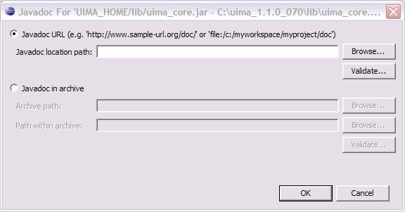 |
Once you do this, Eclipse can show you Javadocs for UIMA APIs as you work. To see the Javadoc for a UIMA API, you can hover over the API class or method, or select it and press shift-F2, or use the menu Navigate → Open External Javadoc, or open the Javadoc view (Window → Show View → Other → Java → Javadoc).
In a similar manner, you can attach the source for the UIMA framework, if you download the source distribution. The source corresponding to particular releases is available from the Apache UIMA web site (http://uima.apache.org) on the downloads page.
1.1. Using named Eclipse User Libraries
You can also create a named "user library" in Eclipse containing the UIMA Jars, and attach the Javadocs (or optionally, the sources); this named library is saved in the Eclipse workspace. Once created, it can be added to the classpath of newly created Eclipse projects.
Use the menu option Project → Properties → Java Build Path, and then pick the Libraries tab, and click the Add Library button. Then select User Libraries, click "Next", and pick the library you created for the UIMA Jars.
To create this library in the workspace, use the same menu picks as above, but after you select the User Libraries and click "Next", you can click the "New Library..." button to define your new library. You use the "Add Jars" button and multi-select all the Jars in the lib directory of the UIMA binary distribution. Then you add the Javadoc attachment for each Jar. The path to use is file:/ -- insert the path to your install of UIMA -- /docs/api. After you do this for the first Jar, you can copy this string to the clipboard and paste it into the rest of the Jars.
Chapter 2. Component Descriptor Reference
This chapter is the reference guide for the UIMA SDK's Component Descriptor XML schema. A Component Descriptor (also sometimes called a Resource Specifier in the code) is an XML file that either (a) completely describes a component, including all information needed to construct the component and interact with it, or (b) specifies how to connect to and interact with an existing component that has been published as a remote service. Component (also called Resource) is a general term for modules produced by UIMA developers and used by UIMA applications. The types of Components are: Analysis Engines, Collection Readers, CAS Initializers[1], CAS Consumers, and Collection Processing Engines. However, Collection Processing Engine Descriptors are significantly different in format and are covered in a separate chapter, Chapter 3, Collection Processing Engine Descriptor Reference.
Section 2.1, “Notation” describes the notation used in this chapter.
Section 2.2, “Imports” describes the UIMA SDK's import syntax, used to allow XML descriptors to import information from other XML files, to allow sharing of information between several XML descriptors.
Section 2.4, “Analysis Engine Descriptors” describes the XML format for Analysis Engine Descriptors. These are descriptors that completely describe Analysis Engines, including all information needed to construct and interact with them.
Section 2.6, “Collection Processing Component Descriptors” describes the XML format for Collection Processing Component Descriptors. This includes Collection Iterator, CAS Initializer, and CAS Consumer Descriptors.
Section 2.7, “Service Client Descriptors” describes the XML format for Service Client Descriptors, which specify how to connect to and interact with resources deployed as remote services.
Section 2.8, “Custom Resource Specifiers” describes the XML format for Custom Resource Specifiers, which allow you to plug in your own Java class as a UIMA Resource.
2.1. Notation
This chapter uses an informal notation to specify the syntax of Component
Descriptors. The formal syntax is defined by an XML schema definition, which is
contained in the file resourceSpecifierSchema.xsd,
located in the uima-core.jar file.
The notation used in this chapter is:
An ellipsis (...) inside an element body indicates that the substructure of that element has been omitted (to be described in another section of this chapter). An example of this would be:
<analysisEngineMetaData>
...
</analysisEngineMetaData>
An ellipsis immediately after an element indicates that the element type may be may be repeated arbitrarily many times. For example:
<parameter>[String]</parameter>
<parameter>[String]</parameter>
...
indicates that there may be arbitrarily many parameter elements in this context.
Bracketed expressions (e.g.
[String]) indicate the type of value that may be used at that location.A vertical bar, as in
true|false, indicates alternatives. This can be applied to literal values, bracketed type names, and elements.Which elements are optional and which are required is specified in prose, not in the syntax definition.
2.2. Imports
The UIMA SDK defines a particular syntax for XML descriptors to import information from other XML files. When one of the following appears in an XML descriptor:
<import location="[URL]" /> or
<import name="[Name]" />
it indicates that information from a separate XML file is being imported. Note that imports are allowed only in certain places in the descriptor. In the remainder of this chapter, it will be indicated at which points imports are allowed.
If an import specifies a location attribute, the value of
that attribute specifies the URL at which the XML file to import will be found. This can be
a relative URL, which will be resolved relative to the descriptor containing the
import element, or an absolute URL. Relative URLs can be written
without a protocol/scheme (e.g., “file:”), and without a host machine
name. In this case the relative URL might look something like
org/apache/myproj/MyTypeSystem.xml.
An absolute URL is written with one of the following prefixes, followed by a path
such as org/apache/myproj/MyTypeSystem.xml:
file:/ ← has no network address
file:/// ← has an empty network address
file://some.network.address/
For more information about URLs, please read the javadoc information for the Java class “URL”.
If an import specifies a name attribute, the value of that
attribute should take the form of a Java-style dotted name (e.g.
org.apache.myproj.MyTypeSystem). An .xml file with this name
will be searched for in the classpath or datapath (described below). As in Java, the dots
in the name will be converted to file path separators. So an import specifying the
example name in this paragraph will result in a search for
org/apache/myproj/MyTypeSystem.xml in the classpath or
datapath.
The datapath works similarly to the classpath but can be set programmatically through the resource manager API. Application developers can specify a datapath during initialization, using the following code:
ResourceManager resMgr = UIMAFramework.newDefaultResourceManager();
resMgr.setDataPath(yourPathString);
AnalysisEngine ae = UIMAFramework.produceAE(desc, resMgr, null);
The default datapath for the entire JVM can be set via the
uima.datapath Java system property, but this feature should
only be used for standalone applications that don't need to run in the same JVM as
other code that may need a different datapath.
Previous versions of UIMA also supported XInclude. That support didn't work in many situations, and it is no longer supported. To include other files, please use <import>.
2.3. Type System Descriptors
A Type System Descriptor is used to define the types and features that can be represented in the CAS. A Type System Descriptor can be imported into an Analysis Engine or Collection Processing Component Descriptor.
The basic structure of a Type System Descriptor is as follows:
<typeSystemDescription xmlns="http://uima.apache.org/resourceSpecifier">

  <name> [String] </name>
  <description>[String]</description>
  <version>[String]</version>
  <vendor>[String]</vendor>

  <imports>
    <import ...>
    ...
  </imports>

  <types>
    <typeDescription>
      ...
    </typeDescription>

    ...

  </types>

</typeSystemDescription>
All of the subelements are optional.
2.3.1. Imports
The imports section allows this descriptor to import
types from other type system descriptors. The import syntax is described in Section 2.2, “Imports”. A type system may import any number of other type
systems and then define additional types which refer to imported types. Circular
imports are allowed.
2.3.2. Types
The types element contains zero or more
typeDescription elements. Each
typeDescription has the form:
<typeDescription>
  <name>[TypeName]</name>
  <description>[String]</description>
  <supertypeName>[TypeName]</supertypeName>
  <features>
    ...
  </features>
</typeDescription>
The name element contains the name of the type. A
[TypeName] is a dot-separated list of names, where each name
consists of a letter followed by any number of letters, digits, or underscores.
TypeNames are case sensitive. Letter and digit are as defined
by Java; therefore, any Unicode letter or digit may be used (subject to the character
encoding defined by the descriptor file's XML header). The name following the
final dot is considered to be the “short name” of the type; the
preceding portion is the namespace (analogous to the package.class syntax used in
Java). Namespaces beginning with uima are reserved and should not be used. Examples
of valid type names are:
test.TokenAnnotation
org.myorg.TokenAnnotation
com.my_company.proj123.TokenAnnotation
These would all be considered distinct types since they have different
namespaces. Best practice here is to follow the normal Java naming conventions of
having namespaces be all lowercase, with the short type names having an initial
capital, but this is not mandated, so ABC.mYtyPE is an allowed
type name. While type names without namespaces (e.g.
TokenAnnotation alone) are allowed, but discouraged because
naming conflicts can then result when combining annotators that use different
type systems.
The description element contains a textual description
of the type. The supertypeName element contains the name of the
type from which it inherits (this can be set to the name of another user-defined type,
or it may be set to any built-in type which may be subclassed, such as
uima.tcas.Annotation for a new annotation
type or uima.cas.TOP for a new type that is not
an annotation). All three of these elements are required.
2.3.3. Features
The features element of a
typeDescription is required only if the type we are specifying
introduces new features. If the features element is present,
it contains zero or more featureDescription elements, each of
which has the form:
<featureDescription>
  <name>[Name]</name>
  <description>[String]</description>
  <rangeTypeName>[Name]</rangeTypeName>
  <elementType>[Name]</elementType>
  <multipleReferencesAllowed>true|false</multipleReferencesAllowed>
</featureDescription>
A feature's name follows the same rules as a type short name – a letter followed by any number of letters, digits, or underscores. Feature names are case sensitive.
The feature's rangeTypeName specifies the type of
value that the feature can take. This may be the name of any type defined in your type
system, or one of the predefined types. All of the predefined types have names that are
prefixed with uima.cas or uima.tcas,
for example:
uima.cas.TOP
uima.cas.String
uima.cas.Long
uima.cas.FSArray
uima.cas.StringList
uima.tcas.Annotation.
For a complete list of predefined types, see the CAS API documentation.
The elementType of a feature is optional, and applies only
when the rangeTypeName is
uima.cas.FSArray or uima.cas.FSList
The elementType specifies what type of value can be assigned as
an element of the array or list. This must be the name of a non-primitive type. If
omitted, it defaults to uima.cas.TOP, meaning that any
FeatureStructure can be assigned as an element the array or list. Note: depending on
the CAS Interface that you use in your code, this constraint may or may not be
enforced.
Note: At run time, the elementType is available from a runtime Feature object
(using the a_feature_object.getRange().getComponentType() method)
only when specified for the uima.cas.FSArray ranges; it isn't
available for uima.cas.FSList ranges.
The multipleReferencesAllowed feature is optional, and
applies only when the rangeTypeName is an array or list type (it
applies to arrays and lists of primitive as well as non-primitive types). Setting
this to false (the default) indicates that this feature has exclusive ownership of
the array or list, so changes to the array or list are localized. Setting this to true
indicates that the array or list may be shared, so changes to it may affect other
objects in the CAS. Note: there is currently no guarantee that the framework will
enforce this restriction. However, this setting may affect how the CAS is
serialized.
2.3.4. String Subtypes
There is one other special type that you can declare – a subset of the String type that specifies a restricted set of allowed values. This is useful for features that can have only certain String values, such as parts of speech. Here is an example of how to declare such a type:
<typeDescription>
  <name>PartOfSpeech</name>
  <description>A part of speech.</description>
  <supertypeName>uima.cas.String</supertypeName>
  <allowedValues>
    <value>
      <string>NN</string>
      <description>Noun, singular or mass.</description>
    </value>
    <value>
      <string>NNS</string>
      <description>Noun, plural.</description>
    </value>
    <value>
      <string>VB</string>
      <description>Verb, base form.</description>
    </value>
    ...
  </allowedValues>
</typeDescription>
2.4. Analysis Engine Descriptors
Analysis Engine (AE) descriptors completely describe Analysis Engines. There are two basic types of Analysis Engines – Primitive and Aggregate. A Primitive Analysis Engine is a container for a single annotator, where as an Aggregate Analysis Engine is composed of a collection of other Analysis Engines. (For more information on this and other terminology, see Chapter 2, UIMA Conceptual Overview).
Both Primitive and Aggregate Analysis Engines have descriptors, and the two types of descriptors have some similarities and some differences. Section 2.4.1, “Primitive Analysis Engine Descriptors” discusses Primitive Analysis Engine descriptors. Section 2.4.2, “Aggregate Analysis Engine Descriptors” then describes how Aggregate Analysis Engine descriptors are different.
2.4.1. Primitive Analysis Engine Descriptors
2.4.1.1. Basic Structure
<?xml version="1.0" encoding="UTF-8" ?>
<analysisEngineDescription
        xmlns="http://uima.apache.org/resourceSpecifier">
  <frameworkImplementation>org.apache.uima.java</frameworkImplementation>

  <primitive>true</primitive>
  <annotatorImplementationName> [String] </annotatorImplementationName>

  <analysisEngineMetaData>
    ...
  </analysisEngineMetaData>

  <externalResourceDependencies>
    ...
  </externalResourceDependencies>

  <resourceManagerConfiguration>
    ...
  </resourceManagerConfiguration>

</analysisEngineDescription>
The document begins with a standard XML header. The recommended root tag is
<analysisEngineDescription>, although
<taeDescription> is also allowed for backwards
compatibility.
Within the root element we declare that we are using the XML namespace
http://uima.apache.org/resourceSpecifier. It is
required that this namespace be used; otherwise, the descriptor will not be able to
be validated for errors.
The first subelement,
<frameworkImplementation>, currently must have
the value org.apache.uima.java, or
org.apache.uima.cpp. In future versions, there may be
other framework implementations, or perhaps implementations produced by other
vendors.
The second subelement, <primitive>, contains
the Boolean value true, indicating that this XML document
describes a Primitive Analysis Engine.
The next subelement,
<annotatorImplementationName> is how the UIMA framework
determines which annotator class to use. This should contain a fully-qualified
Java class name for Java implementations, or the name of a .dll or .so file for C++
implementations.
The <analysisEngineMetaData> object contains
descriptive information about the analysis engine and what it does. It is
described in Section 2.4.1.2, “Analysis Engine MetaData”.
The <externalResourceDependencies> and
<resourceManagerConfiguration> elements declare
the external resource files that the analysis engine relies
upon. They are optional and are described in Section 2.4.1.10, “External Resource Dependencies” and Section 2.4.1.11, “Resource Manager Configuration”.
2.4.1.2. Analysis Engine MetaData
<analysisEngineMetaData>
  <name> [String] </name>
  <description>[String]</description>
  <version>[String]</version>
  <vendor>[String]</vendor>

  <configurationParameters> ...  </configurationParameters>

  <configurationParameterSettings>
    ...
  </configurationParameterSettings>

  <typeSystemDescription> ... </typeSystemDescription>

  <typePriorities> ... </typePriorities>

  <fsIndexCollection> ... </fsIndexCollection>

  <capabilities> ... </capabilities>

  <operationalProperties> ... </operationalProperties>

</analysisEngineMetaData>
The analysisEngineMetaData element contains four
simple string fields – name,
description, version, and
vendor. Only the name field is
required, but providing values for the other fields is recommended. The
name field is just a descriptive name meant to be read by
users; it does not need to be unique across all Analysis Engines.
The other sub-elements –
configurationParameters,
configurationParameterSettings,
typeSystemDescription,
typePriorities, fsIndexes,
capabilities and
operationalProperties are described in the following
sections. The only one of these that is required is
capabilities; the others are optional.
2.4.1.3. Configuration Parameter Declaration
Configuration Parameters are made available to annotator
implementations and applications by the following interfaces:
AnnotatorContext [2] (passed as an argument to the
initialize() method of a version 1 annotator),
ConfigurableResource (every Analysis Engine
implements this interface), and the UimaContext (passed
as an argument to the initialize() method of a version 2 annotator) (you can get
this from any resource, including Analysis Engines, using the method
getUimaContext()).
Use AnnotatorContext within version 1 annotators and UimaContext for version 2 annotators and outside of annotators (for instance, in CasConsumers, or the containing application) to access configuration parameters.
Configuration parameters are set from the corresponding elements in the XML descriptor for the application. If you need to programmatically change parameter settings within an application, you can use methods in ConfigurableResource; if you do this, you need to call reconfigure() afterwards to have the UIMA framework notify all the contained analysis components that the parameter configuration has changed (the analysis engine's reinitialize() methods will be called). Note that in the current implementation, only integrated deployment components have configuration parameters passed to them; remote components obtain their parameters from their remote startup environment. This will likely change in the future.
There are two ways to specify the
<configurationParameters> section – as a
list of configuration parameters or a list of groups. A list of parameters, which
are not part of any group, looks like this:
<configurationParameters>
  <configurationParameter>
    <name>[String]</name>
    <description>[String]</description>
    <type>String|Integer|Float|Boolean</type>
    <multiValued>true|false</multiValued>
    <mandatory>true|false</mandatory>
    <overrides>
      <parameter>[String]</parameter>
      <parameter>[String]</parameter>
        ...
    </overrides>
  </configurationParameter>
  <configurationParameter>
    ...
  </configurationParameter>
    ...
</configurationParameters>
For each configuration parameter, the following are specified:
name – the name by which the annotator code refers to the parameter. All parameters declared in an analysis engine descriptor must have distinct names. (required). The name is composed of normal Java identifier characters.
description – a natural language description of the intent of the parameter (optional)
type – the data type of the parameter's value – must be one of
String,Integer,Float, orBoolean(required).multiValued –
trueif the parameter can take multiple-values (an array),falseif the parameter takes only a single value (optional, defaults to false).mandatory –
trueif a value must be provided for the parameter (optional, defaults to false).overrides – this is used only in aggregate Analysis Engines, but is included here for completeness. See Section 2.4.2.4, “Configuration Parameter Overrides” for a discussion of configuration parameter overriding in aggregate Analysis Engines. (optional)
A list of groups looks like this:
<configurationParameters defaultGroup="[String]"
    searchStrategy="none|default_fallback|language_fallback" >

  <commonParameters>
    [zero or more parameters]
  </commonParameters>

  <configurationGroup names="name1 name2 name3 ...">
    [zero or more parameters]
  </configurationGroup>

  <configurationGroup names="name4 name5 ...">
    [zero or more parameters]
  </configurationGroup>

  ...

</configurationParameters>
Both the <commonParameters> and
<configurationGroup> elements contain zero or
more <configurationParameter> elements, with
the same syntax described above.
The <commonParameters> element declares
parameters that exist in all groups. Each
<configurationGroup> element has a names
attribute, which contains a list of group names separated by whitespace (space
or tab characters). Names consist of any number of non-whitespace characters;
however the Component Descriptor Editor tool restricts this to be normal Java
identifiers, including the period (.) and the dash (-). One configuration group
will be created for each name, and all of the groups will contain the same set of
parameters.
The defaultGroup attribute specifies the name of the
group to be used in the case where an annotator does a lookup for a configuration
parameter without specifying a group name. It may also be used as a fallback if the
annotator specifies a group that does not exist – see below.
The searchStrategy attribute determines the action
to be taken when the context is queried for the value of a parameter belonging to a
particular configuration group, if that group does not exist or does not contain
a value for the requested parameter. There are currently three possible values:
none – there is no fallback; return null if there is no value in the exact group specified by the user.
default_fallback – if there is no value found in the specified group, look in the default group (as defined by the
defaultattribute)language_fallback – this setting allows for a specific use of configuration parameter groups where the groups names correspond to ISO language and country codes (for an example, see below). The fallback sequence is:
<lang>_<country>_<region> →
                <lang>_<country> → <lang> →
                <default>.
Example
<configurationParameters defaultGroup="en"
        searchStrategy="language_fallback">

  <commonParameters>
    <configurationParameter>
      <name>DictionaryFile</name>
      <description>Location of dictionary for this
           language</description>
      <type>String</type>
      <multiValued>false</multiValued>
      <mandatory>false</mandatory>
    </configurationParameter>
  </commonParameters>

  <configurationGroup names="en de en-US"/>

  <configurationGroup names="zh">
    <configurationParameter>
      <name>DBC_Strategy</name>
      <description>Strategy for dealing with double-byte
          characters.</description>
      <type>String</type>
      <multiValued>false</multiValued>
      <mandatory>false</mandatory>
    </configurationParameter>
  </configurationGroup>

</configurationParameters>
In this example, we are declaring a DictionaryFile
parameter that can have a different value for each of the languages that our AE
supports
– English (general), German, U.S. English, and Chinese. For Chinese
only, we also declare a DBC_Strategy
parameter.
We are using the language_fallback search
strategy, so if an annotator requests the dictionary file for the
en-GB (British English) group, we will fall back to the
more general en group.
Since we have defined en as the default group, this
value will be returned if the context is queried for the
DictionaryFile parameter without specifying any
group name, or if a nonexistent group name is specified.
2.4.1.4. Configuration Parameter Settings
If no configuration groups were declared, the
<configurationParameterSettings> element
looks like this:
<configurationParameterSettings>
  <nameValuePair>
    <name>[String]</name>
    <value>
      <string>[String]</string>  |
      <integer>[Integer]</integer> |
      <float>[Float]</float> |
      <boolean>true|false</boolean>  |
      <array> ... </array>
    </value>
  </nameValuePair>

  <nameValuePair>
    ...
  </nameValuePair>
  ...
</configurationParameterSettings>
There are zero or more nameValuePair elements. Each
nameValuePair contains a name (which refers to one of the
configuration parameters) and a value for that parameter.
The value element contains an element that matches
the type of the parameter. For single-valued parameters, this is either
<string>, <integer>
, <float>, or
<boolean>. For multi-valued parameters, this is
an <array> element, which then contains zero or
more instances of the appropriate type of primitive value, e.g.:
<array><string>One</string><string>Two</string></array>
If configuration groups were declared, then the
<configurationParameterSettings> element
looks like this:
<configurationParameterSettings>

  <settingsForGroup name="[String]">
    [one or more <nameValuePair> elements]
  </settingsForGroup>

  <settingsForGroup name="[String]">
    [one or more <nameValuePair> elements]
  </settingsForGroup>

...

</configurationParameterSettings>
where each <settingsForGroup> element has a name
that matches one of the configuration groups declared under the
<configurationParameters> element and contains
the parameter settings for that group.
Example
Here are the settings that correspond to the parameter declarations in the previous example:
<configurationParameterSettings>

  <settingsForGroup name="en">
    <nameValuePair>
      <name>DictionaryFile</name>
      <value><string>resourcesEnglishdictionary.dat></string></value>
    </nameValuePair>
  </settingsForGroup>

  <settingsForGroup name="en-US">
    <nameValuePair>
      <name>DictionaryFile</name>
      <value><string>resourcesEnglish_USdictionary.dat</string></value>
    </nameValuePair>
  </settingsForGroup>

  <settingsForGroup name="de">
    <nameValuePair>
      <name>DictionaryFile</name>
      <value><string>resourcesDeutschdictionary.dat</string></value>
    </nameValuePair>
  </settingsForGroup>

  <settingsForGroup name="zh">
    <nameValuePair>
      <name>DictionaryFile</name>
      <value><string>resourcesChinesedictionary.dat</string></value>
    </nameValuePair>

    <nameValuePair>
      <name>DBC_Strategy</name>
      <value><string>default</string></value>
    </nameValuePair>

  </settingsForGroup>

</configurationParameterSettings>
2.4.1.5. Type System Definition
<typeSystemDescription>

  <name> [String] </name>
  <description>[String]</description>
  <version>[String]</version>
  <vendor>[String]</vendor>

  <imports>
    <import ...>
    ...
  </imports>

  <types>
    <typeDescription>
      ...
    </typeDescription>

    ...

  </types>

</typeSystemDescription>
A typeSystemDescription element defines a type
system for an Analysis Engine. The syntax for the element is described in Section 2.3, “Type System Descriptors”.
The recommended usage is to import an external type
system, using the import syntax described in Section 2.2, “Imports”
of this chapter. For example:
<typeSystemDescription>
  <imports>
    <import location="MySharedTypeSystem.xml">
  </imports>
</typeSystemDescription>
This allows several AEs to share a single type system definition. The file
MySharedTypeSystem.xml would then contain the full
type system information, including the name,
description, vendor,
version, and types.
2.4.1.6. Type Priority Definition
<typePriorities>
  <name> [String] </name>
  <description>[String]</description>
  <version>[String]</version>
  <vendor>[String]</vendor>

  <imports>
    <import ...>
    ...
  </imports>

  <priorityLists>
    <priorityList>
      <type>[TypeName]</type>
      <type>[TypeName]</type>
        ...
    </priorityList>

    ...

  </priorityLists>
</typePriorities>
The <typePriorities> element contains
zero or more <priorityList> elements; each
<priorityList> contains zero or more types.
Like a type system, a type priorities definition may also declare a name,
description, version, and vendor, and may import other type priorities. See
Section 2.2, “Imports” for the import syntax.
Type priority is used when iterating over feature structures in the CAS.
For example, if the CAS contains a Sentence annotation
and a Paragraph annotation with the same span of text
(i.e. a one-sentence paragraph), which annotation should be returned first
by an iterator? Probably the Paragraph, since it is conceptually
“bigger,” but the framework does not know that and must be
explicitly told that the Paragraph annotation has priority over the Sentence
annotation, like this:
<typePriorities>
  <priorityList>
    <type>org.myorg.Paragraph</type>
    <type>org.myorg.Sentence</type>
  </priorityList>
</typePriorities>
All of the <priorityList> elements defined
in the descriptor (and in all component descriptors of an aggregate analysis
engine descriptor) are merged to produce a single priority list.
Subtypes of types specified here are also ordered, unless overridden by another user-specified type ordering. For example, if you specify type A comes before type B, then subtypes of A will come before subtypes of B, unless there is an overriding specification which declares some subtype of B comes before some subtype of A.
If there are inconsistencies between the priority list (type A declared before type B in one priority list, and type B declared before type A in another), the framework will throw an exception.
User defined indexes may declare if they wish to use the type priority or not; see the next section.
2.4.1.7. Index Definition
<fsIndexCollection>

  <name>[String]</name>
  <description>[String]</description>
  <version>[String]</version>
  <vendor>[String]</vendor>

  <imports>
    <import ...>
    ...
  </imports>

  <fsIndexes>

    <fsIndexDescription>
      ...
    </fsIndexDescription>

    <fsIndexDescription>
      ...
    </fsIndexDescription>

  </fsIndexes>

</fsIndexCollection>
The fsIndexCollection element declares Feature Structure
Indexes, each of which defined an index that holds feature structures of a given type.
Information in the CAS is always accessed through an index. There is a built-in default annotation
index declared which can be used to access instances of type
uima.tcas.Annotation (or its subtypes), sorted based on their
begin and end features. For all other types, there is a
default, unsorted (bag) index. If there is a need for a specialized index it must be declared in this
element of the descriptor. See Section 4.7, “Indexes and Iterators” for details on FS indexes.
Like type systems and type priorities, an
fsIndexCollection can declare a
name, description,
vendor, and version, and may
import other fsIndexCollections. The import syntax is
described in Section 2.2, “Imports”.
An fsIndexCollection may also define zero or more
fsIndexDescription elements, each of which defines a
single index. Each fsIndexDescription has the form:
<fsIndexDescription>

  <label>[String]</label>
  <typeName>[TypeName]</typeName>
  <kind>sorted|bag|set</kind>

  <keys>

    <fsIndexKey>
      <featureName>[Name]</featureName>
      <comparator>standard|reverse</comparator>
    </fsIndexKey>

    <fsIndexKey>
      <typePriority/>
    </fsIndexKey>

    ...

  </keys>
</fsIndexDescription>
The label element defines the name by which
applications and annotators refer to this index. The
typeName element contains the name of the type that will
be contained in this index. This must match one of the type names defined in the
<typeSystemDescription>.
There are three possible values for the
<kind> of index. Sorted indexes enforce an
ordering of feature structures, and may contain duplicates. Bag indexes do
not enforce ordering, and also may contain duplicates. Set indexes do not
enforce ordering and may not contain duplicates. If the <kind>element is omitted, it will default to
sorted, which is the most common type of index.
Note
There is usually no need to explicitly declare a Bag index in your descriptor. As of UIMA v2.1, if you do not declare any index for a type (or any of its supertypes), a Bag index will be automatically created.
An index may define zero or more keys. These keys determine the sort order of the feature structures within a sorted index, and determine equality for set indexes. Bag indexes do not use keys, and equality is determined by Feature Structure identity (that is, two elements are considered equal if and only if they are exactly the same feature structure, located in the same place in the CAS). Keys are ordered by precedence – the first key is evaluated first, and subsequent keys are evaluated only if necessary.
Each key is represented by an fsIndexKey element.
Most fsIndexKeys contains a
featureName and a comparator.
The featureName must match the name of one of the
features for the type specified in the
<typeName> element for this index. The
comparator defines how the features will be compared – a value of
standard means that features will be compared using the
standard comparison for their data type (e.g. for numerical types, smaller
values precede larger values, and for string types, Unicode string
comparison is performed). A value of reverse means that
features will be compared using the reverse of the standard comparison (e.g.
for numerical types, larger values precede smaller values, etc.). For Set
indexes, the comparator direction is ignored – the keys are only used
for the equality testing.
Each key used in comparisons must refer to a feature whose range type is String, Float, or Integer.
There is a second type of a key, one which contains only the
<typePriority/>. When this key is used, it
indicates that Feature Structures will be compared using the type priorities
declared in the <typePriorities> section of the
descriptor.
2.4.1.8. Capabilities
<capabilities>
  <capability>

    <inputs>
      <type allAnnotatorFeatures="true|false"[TypeName]</type>
      ...
      <feature>[TypeName]:[Name]</feature>
      ...
    </inputs>

    <outputs>
      <type allAnnotatorFeatures="true|false"[TypeName]</type>
      ...
      <feature>[TypeName]:[Name]</feature>
      ...
    </output>

    <inputSofas>
      <sofaName>[name]</sofaName>
      ...
    </inputSofas>

    <outputSofas>
      <sofaName>[name]</sofaName>
      ...
    </outputSofas>

    <languagesSupported>
      <language>[ISO Language ID]</language>
        ...
    </languagesSupported>
  </capability>

  <capability>
    ...
  </capability>

  ...

</capabilities>
The capabilities definition is used by the UIMA Framework in several ways, including setting up the Results Specification for process calls, routing control for aggregates based on language, and as part of the Sofa mapping function.
The capabilities element contains one or more
capability elements. In Version 2 and onwards, only one
capability set should be used (multiple sets will continue to work for a while,
but they're not logically consistently supported).
Each capability contains
inputs, outputs,
languagesSupported, inputSofas, and outputSofas.
Inputs and outputs element are required (though they may be empty);
<languagesSupported>, <inputSofas>,
and <outputSofas> are optional.
Both inputs and outputs may contain a mixture of type and feature elements.
<type...> elements contain the name of one
of the types defined in the type system or one of the built in types. Declaring a
type as an input means that this component expects instances of this type to be
in the CAS when it receives it to process. Declaring a type as an output means
that this component creates new instances of this type in the CAS.
There is an optional attribute
allAnnotatorFeatures, which defaults to false if
omitted. The Component Descriptor Editor tool defaults this to true when a new
type is added to the list of inputs and/or outputs. When this attribute is true,
it specifies that all of the type's features are also declared as input or
output. Otherwise, the features that are required as inputs or populated as
outputs must be explicitly specified in feature elements.
<feature...> elements contain the
“fully-qualified” feature name, which is the type name
followed by a colon, followed by the feature name, e.g.
org.myorg.TokenAnnotation:lemma.
<feature...> elements in the
<inputs> section must also have a corresponding
type declared as an input. In output sections, this is not required. If the type
is not specified as an output, but a feature for that type is, this means that
existing instances of the type have the values of the specified features
updated. Any type mentioned in a <feature>
element must be either specified as an input or an output or both.
language elements contain one of the ISO language
identifiers, such as en for English, or
en-US for the United States dialect of English.
The list of language codes can be found here: http://www.ics.uci.edu/pub/ietf/http/related/iso639.txt and the country codes here: http://www.chemie.fu-berlin.de/diverse/doc/ISO_3166.html
<inputSofas> and
<outputSofas> declare sofa names used by this
component. All Sofa names must be unique within a particular capability set. A
Sofa name must be an input or an output, and cannot be both. It is an error to have a
Sofa name declared as an input in one capability set, and also have it declared
as an output in another capability set.
A <sofaName> is written as a simple
Java-style identifier, without any periods in the name, except that it may be
written to end in “.*”. If written in this
manner, it specifies a set of Sofa names, all of which start with the base name
(the part before the .*) followed by a period and then an arbitrary Java
identifier (without periods). This form is used to specify in the descriptor
that the component could generate an arbitrary number of Sofas, the exact
names and numbers of which are unknown before the component is run.
2.4.1.9. OperationalProperties
Components can specify specific operational properties that can be useful in deployment. The following are available:
<operationalProperties>
  <modifiesCas> true|false </modifiesCas>
  <multipleDeploymentAllowed> true|false </multipleDeploymentAllowed>
  <outputsNewCASes> true|false </outputsNewCASes>
</operationalProperties>
ModifiesCas, if false, indicates that this
component does not modify the CAS. If it is not specified, the default value is
true except for CAS Consumer components.
multipleDeploymentAllowed, if true, allows the
component to be deployed multiple times to increase performance throught
scale-out techniques. If it is not specified, the default value is true,
except for CAS Consumer and Collection Reader components.
Note
If you wrap one or more CAS Consumers inside an aggregate as the only
components, you must explicitly specify in the aggregate the
multipleDeploymentAllowed property as false (assuming the CAS Consumer
components take the default here); otherwise the framework will complain about inconsistent
settings for these.
outputsNewCASes, if true, allows the component to
create new CASes during processing, for example to break a large artifact into
smaller pieces. See Chapter 7, CAS Multiplier Developer's Guide for details.
2.4.1.10. External Resource Dependencies
<externalResourceDependencies>
  <externalResourceDependency>
    <key>[String]</key>
    <description>[String] </description>
    <interfaceName>[String]</interfaceName>
    <optional>true|false</optional>
  </externalResourceDependency>

  <externalResourceDependency>
    ...
  </externalResourceDependency>

  ...

</externalResourceDependencies>
A primitive annotator may declare zero or more
<externalResourceDependency> elements. Each
dependency has the following elements:
key– the string by which the annotator code will attempt to access the resource. Must be unique within this annotator.description– a textual description of the dependencyinterfaceName– the fully-qualified name of the Java interface through which the annotator will access the data. This is optional. If not specified, the annotator can only get an InputStream to the data.optional– whether the resource is optional. If false, an exception will be thrown if no resource is assigned to satisfy this dependency. Defaults to false.
2.4.1.11. Resource Manager Configuration
<resourceManagerConfiguration>

  <name>[String]</name>
  <description>[String]</description>
  <version>[String]</version>
  <vendor>[String]</vendor>

  <imports>
    <import ...>
    ...
  </imports>

  <externalResources>

    <externalResource>
      <name>[String]</name>
      <description>[String]</description>
      <fileResourceSpecifier>
        <fileUrl>[URL]</fileUrl>
      </fileResourceSpecifier>
      <implementationName>[String]</implementationName>
    </externalResource>
    ...
  </externalResources>

  <externalResourceBindings>
    <externalResourceBinding>
      <key>[String]</key>
      <resourceName>[String]</resourceName>
    </externalResourceBinding>
    ...
  </externalResourceBindings>

</resourceManagerConfiguration>
This element declares external resources and binds them to annotators' external resource dependencies.
The resourceManagerConfiguration element may
optionally contain an import, which allows resource
definitions to be stored in a separate (shareable) file. See Section 2.2, “Imports” for details.
The externalResources element contains zero or
more externalResource elements, each of which
consists of:
name– the name of the resource. This name is referred to in the bindings (see below). Resource names need to be unique within any Aggregate Analysis Engine or Collection Processing Engine, so the Java-likeorg.myorg.mycomponent.MyResourcesyntax is recommended.description– English description of the resourceResource Specifier – Declares the location of the resource. There are different possibilities for how this is done (see below).
implementationName– The fully-qualified name of the Java class that will be instantiated from the resource data. This is optional; if not specified, the resource will be accessible as an input stream to the raw data. If specified, the Java class must implement theinterfaceNamethat is specified in the External Resource Dependency to which it is bound.
One possibility for the resource specifier is a
<fileResourceSpecifier>, as shown above. This
simply declares a URL to the resource data. This support is built on the Java
class URL and its method URL.openStream(); it supports the protocols
“file”, “http” and “jar” (for
referring to files in jars) by default, and you can plug in handlers for other
protocols. The URL has to start with file: (or some other protocol). It is
relative to either the classpath or the “data path”. The data
path works like the classpath but can be set programmatically via
ResourceManager.setDataPath(). Setting the Java
System property uima.datapath also works.
file:com/apache.d.txt is a relative path;
relative paths for resources are resolved using the classpath and/or the
datapath. For the file protocol, URLs starting with file:/ or file:/// are
absolute. Note that file://org/apache/d.txt is NOT an
absolute path starting with “org”. The “//”
indicates that what follows is a host name. Therefore if you try to use this URL
it will complain that it can't connect to the host “org”
Another option is a
<fileLanguageResourceSpecifier>, which is
intended to support resources, such as dictionaries, that depend on the
language of the document being processed. Instead of a single URL, a prefix and
suffix are specified, like this:
<fileLanguageResourceSpecifier>
  <fileUrlPrefix>file:FileLanguageResource_implTest_data_</fileUrlPrefix>
  <fileUrlSuffix>.dat</fileUrlSuffix>
</fileLanguageResourceSpecifier>
The URL of the actual resource is then formed by concatenating the prefix,
the language of the document (as an ISO language code, e.g.
en or en-US
– see Section 2.4.1.8, “Capabilities” for more
information), and the suffix.
A third option is a customResourceSpecifier, which allows
you to plug in an arbitrary Java class. See Section 2.8, “Custom Resource Specifiers”
for more information.
The externalResourceBindings element declares
which resources are bound to which dependencies. Each
externalResourceBinding consists of:
key– identifies the dependency. For a binding declared in a primitive analysis engine descriptor, this must match the value of thekeyelement of one of theexternalResourceDependencyelements. Bindings may also be specified in aggregate analysis engine descriptors, in which case a compound key is used – see Section 2.4.2.5, “External Resource Bindings” .resourceName– the name of the resource satisfying the dependency. This must match the value of thenameelement of one of theexternalResourcedeclarations.
A given resource dependency may only be bound to one external resource; one external resource may be bound to many dependencies – to allow resource sharing.
2.4.1.12. Environment Variable References
In several places throughout the descriptor, it is possible to reference
environment variables. In Java, these are actually references to Java system
properties. To reference system environment variables from a Java analysis
engine you must pass the environment variables into the Java virtual machine
by using the -D option on the java
command line.
The syntax for environment variable references is
<envVarRef>[VariableName]</envVarRef>
, where [VariableName] is any valid Java system property name. Environment
variable references are valid in the following places:
The value of a configuration parameter (String-valued parameters only)
The
<annotatorImplementationName>element of a primitive AE descriptorThe
<name>element within<analysisEngineMetaData>Within a
<fileResourceSpecifier>or<fileLanguageResourceSpecifier>
For example, if the value of a configuration parameter were specified as:
<string><envVarRef>TEMP_DIR</envVarRef>/temp.dat</string>
, and the value of the TEMP_DIR Java System property were
c:/temp, then the configuration parameter's
value would evaluate to c:/temp/temp.dat.
Note
The Component Descriptor Editor does not support
environment variable references. If you need to, however, you
can use the source tab view in the CDE to manually
add this notation.
2.4.2. Aggregate Analysis Engine Descriptors
Aggregate Analysis Engines do not contain an annotator, but instead contain one or more component (also called delegate) analysis engines.
Aggregate Analysis Engine Descriptors maintain most of the same structure as Primitive Analysis Engine Descriptors. The differences are:
An Aggregate Analysis Engine Descriptor contains the element
<primitive>false</primitive>rather than<primitive>true</primitive>.An Aggregate Analysis Engine Descriptor must not include a
<annotatorImplementationName>element.In place of the
<annotatorImplementationName>, an Aggregate Analysis Engine Descriptor must have a<delegateAnalysisEngineSpecifiers>element. See Section 2.4.2.1, “Delegate Analysis Engine Specifiers”.An Aggregate Analysis Engine Descriptor may provide a
<flowController>element immediately following the<delegateAnalysisEngineSpecifiers>. Section 2.4.2.2, “FlowController”.Under the analysisEngineMetaData element, an Aggregate Analysis Engine Descriptor may specify an additional element --
<flowConstraints>. See Section 2.4.2.3, “FlowConstraints”. Typically only one of<flowController>and<flowConstraints>are specified. If both are specified, the<flowController>takes precedence, and the flow controller implementation can use the information in specified in the<flowConstraints>as part of its configuration input.An aggregate Analysis Engine Descriptors must not contain a
<typeSystemDescription>element. The Type System of the Aggregate Analysis Engine is derived by merging the Type System of the Analysis Engines that the aggregate contains.Within aggregate Analysis Engine Descriptors,
<configurationParameter>elements may define<overrides>. See Section 2.4.2.4, “Configuration Parameter Overrides” .External Resource Bindings can bind resources to dependencies declared by any delegate AE within the aggregate. See Section 2.4.2.5, “External Resource Bindings”.
An additional optional element,
<sofaMappings>, may be included.
2.4.2.1. Delegate Analysis Engine Specifiers
<delegateAnalysisEngineSpecifiers>

  <delegateAnalysisEngine key="[String]">
    <analysisEngineDescription>...</analysisEngineDescription> |
    <import .../>
  </delegateAnalysisEngine>

  <delegateAnalysisEngine key="[String]">
    ...
  </delegateAnalysisEngine>

  ...

</delegateAnalysisEngineSpecifiers>
The delegateAnalysisEngineSpecifiers element
contains one or more delegateAnalysisEngine
elements. Each of these must have a unique key, and must contain
either:
A complete
analysisEngineDescriptionelement describing the delegate analysis engine ORAn
importelement giving the name or location of the XML descriptor for the delegate analysis engine (see Section 2.2, “Imports”).
The latter is the much more common usage, and is the only form supported by the Component Descriptor Editor tool.
2.4.2.2. FlowController
<flowController key="[String]">
    <flowControllerDescription>...</flowControllerDescription> |
    <import .../>
  </flowController>
The optional flowController element identifies
the descriptor of the FlowController component that will be used to determine
the order in which delegate Analysis Engine are called.
The key attribute is optional, but recommended; it
assigns the FlowController an identifier that can be used for configuration
parameter overrides, Sofa mappings, or external resource bindings. The key
must not be the same as any of the delegate analysis engine keys.
As with the delegateAnalysisEngine element, the
flowController element may contain either a complete
flowControllerDescription or an
import, but the import is recommended. The Component
Descriptor Editor tool only supports imports here.
2.4.2.3. FlowConstraints
If a <flowController> is not specified, the
order in which delegate Analysis Engines are called within the aggregate
Analysis Engine is specified using the
<flowConstraints> element, which must occur
immediately following the
configurationParameterSettings element. If a
<flowController> is specified, then the
<flowConstraints> are optional. They can be
used to pass an ordering of delegate keys to the
<flowController>.
There are two options for flow constraints --
<fixedFlow> or
<capabilityLanguageFlow>. Each is discussed
in a separate section below.
Fixed Flow
<flowConstraints>
  <fixedFlow>
    <node>[String]</node>
    <node>[String]</node>
    ...
  </fixedFlow>
</flowConstraints>
The flowConstraints element must be included
immediately following the
configurationParameterSettings element.
Currently the flowConstraints element must
contain a fixedFlow element. Eventually, other
types of flow constraints may be possible.
The fixedFlow element contains one or more
node elements, each of which contains an identifier
which must match the key of a delegate analysis engine specified in the
delegateAnalysisEngineSpecifiers
element.
Capability Language Flow
<flowConstraints>
  <capabilityLanguageFlow>
    <node>[String]</node>
    <node>[String]</node>
    ...
  </capabilityLanguageFlow>
</flowConstraints>
If you use <capabilityLanguageFlow>,
the delegate Analysis Engines named by the
<node> elements are called in the given order,
except that a delegate Analysis Engine is skipped if any of the following are
true (according to that Analysis Engine's declared output
capabilities):
It cannot produce any of the aggregate Analysis Engine's output capabilities for the language of the current document.
All of the output capabilities have already been produced by an earlier Analysis Engine in the flow.
For example, if two annotators produce
org.myorg.TokenAnnotation feature structures for
the same language, these feature structures will only be produced by the
first annotator in the list.
Note
The flow analysis uses the specific types that are specified in the output capabilities, without any expansion for subtypes. So, if you expect a type TT and another type SubTT (which is a subtype of TT) in the output, you must include both of them in the output capabilities.
2.4.2.4. Configuration Parameter Overrides
In an aggregate Analysis Engine Descriptor, each
<configurationParameter> element should
contain an <overrides> element, with the
following syntax:
<overrides>

  <parameter>
    [delegateAnalysisEngineKey]/[parameterName]
  </parameter>

  <parameter>
    [delegateAnalysisEngineKey]/[parameterName]
  </parameter>
  ...

</overrides>
Since aggregate Analysis Engines have no code associated with them, the
only way in which their configuration parameters can affect their processing
is by overriding the parameter values of one or more delegate analysis
engines. The <overrides> element determines
which parameters, in which delegate Analysis Engines, are overridden by this
configuration parameter.
For example, consider an aggregate Analysis Engine Descriptor that
contains delegate Analysis Engines with keys
annotator1 and annotator2 (as
declared in the <delegateAnalysisEngine> element – see Section 2.4.2.1, “Delegate Analysis Engine Specifiers”) and also declares a
configuration parameter as follows:
<configurationParameter>
  <name>AggregateParam</name>
  <type>String</type>
  <overrides>
    <parameter>annotator1/param1</parameter>
    <parameter>annotator2/param2</parameter>
  </overrides>
</configurationParameter>
The value of the AggregateParam parameter
(whether assigned in the aggregate descriptor or at runtime by an
application) will override the value of parameter
param1 in annotator1 and also
override the value of parameter param2 in
annotator2. No other parameters will be
affected.
For historical reasons only, if an aggregate Analysis Engine descriptor declares a configuration parameter with no explicit overrides, that parameter will override any parameters having the same name within any delegate analysis engine. This usage is strongly discouraged. The UIMA SDK currently supports this usage but logs a warning message to the log file. This support may be dropped in future versions.
2.4.2.5. External Resource Bindings
Aggregate analysis engine descriptors can declare resource bindings that bind resources to dependencies declared in any of the delegate analysis engines (or their subcomponents, recursively) within that aggregate. This allows resource sharing. Any binding at this level overrides (supersedes) any binding specified by a contained component or their subcomponents, recursively.
For example, consider an aggregate Analysis Engine Descriptor that
contains delegate Analysis Engines with keys
annotator1 and annotator2 (as
declared in the <delegateAnalysisEngine>
element – see Section 2.4.2.1, “Delegate Analysis Engine Specifiers”),
where annotator1 declares a resource dependency with
key myResource and annotator2
declares a resource dependency with key someResource
.
Within that aggregate Analysis Engine Descriptor, the following
resourceManagerConfiguration would bind both of
those dependencies to a single external resource file.
<resourceManagerConfiguration>

  <externalResources>
    <externalResource>
      <name>ExampleResource</name>
      <fileResourceSpecifier>
        <fileUrl>file:MyResourceFile.dat</fileUrl>
      </fileResourceSpecifier>
    </externalResource>
  </externalResources>

  <externalResourceBindings>
    <externalResourceBinding>
      <key>annotator1/myResource</key>
      <resourceName>ExampleResource</resourceName>
    </externalResourceBinding>
    <externalResourceBinding>
      <key>annotator2/someResource</key>
      <resourceName>ExampleResource</resourceName>
    </externalResourceBinding>
  </externalResourceBindings>

</resourceManagerConfiguration>
The syntax for the externalResources declaration
is exactly the same as described previously. In the resource bindings note the
use of the compound keys, e.g. annotator1/myResource.
This identifies the resource dependency key
myResource within the annotator with key
annotator1. Compound resource dependencies can be
multiple levels deep to handle nested aggregate analysis engines.
2.4.2.6. Sofa Mappings
Sofa mappings are specified between Sofa names declared in this
aggregate descriptor as part of the
<capability> section, and the Sofa names
declared in the delegate components. For purposes of the mapping, all the
declarations of Sofas in any of the capability sets contained within the
<capabilities> element are considered
together.
<sofaMappings>
  <sofaMapping>
    <componentKey>[keyName]</componentKey>
    <componentSofaName>[sofaName]</componentSofaName>
    <aggregateSofaName>[sofaName]</aggregateSofaName>
  </sofaMapping>
  ...
</sofaMappings>
The <componentSofaName> may be omitted in the case where the component is not aware of Multiple Views or Sofas. In this case, the UIMA framework will arrange for the specified <aggregateSofaName> to be the one visible to the delegate component.
The <componentKey> is the key name for the component as specified in the list of delegate components for this aggregate.
The sofaNames used must be declared as input or output sofas in some capability set.
2.5. Flow Controller Descriptors
The basic structure of a Flow Controller Descriptor is as follows:
<?xml version="1.0" ?>
<flowControllerDescription
    xmlns="http://uima.apache.org/resourceSpecifier">

  <frameworkImplementation>org.apache.uima.java</frameworkImplementation>

  <implementationName>[ClassName]</implementationName>

  <processingResourceMetaData>
    ...
  </processingResourceMetaData>

  <externalResourceDependencies>
    ...
  </externalResourceDependencies>

  <resourceManagerConfiguration>
    ...
  </resourceManagerConfiguration>

</flowControllerDescription>
The frameworkImplementation element must always be set to
the value org.apache.uima.java.
The implementationName element must contain the
fully-qualified class name of the Flow Controller implementation. This must name a
class that implements the FlowController interface.
The processingResourceMetaData element contains
essentially the same information as a Primitive Analysis Engine Descriptor's
analysisEngineMetaData element, described in Section 2.4.1.2, “Analysis Engine MetaData”.
The externalResourceDependencies and
resourceManagerConfiguration elements are exactly the same as
in Primitive Analysis Engine Descriptors (see Section 2.4.1.10, “External Resource Dependencies” and Section 2.4.1.11, “Resource Manager Configuration”.
2.6. Collection Processing Component Descriptors
There are three types of Collection Processing Components – Collection Readers, CAS Initializers (deprecated as of UIMA Version 2), and CAS Consumers. Each type of component has a corresponding descriptor. The structure of these descriptors is very similar to that of primitive Analysis Engine Descriptors.
2.6.1. Collection Reader Descriptors
The basic structure of a Collection Reader descriptor is as follows:
<?xml version="1.0" ?>
<collectionReaderDescription
    xmlns="http://uima.apache.org/resourceSpecifier">

  <frameworkImplementation>org.apache.uima.java</frameworkImplementation>
  <implementationName>[ClassName]</implementationName>

  <processingResourceMetaData>
    ...
  </processingResourceMetaData>

  <externalResourceDependencies>
   ...
  </externalResourceDependencies>

  <resourceManagerConfiguration>

   ...

  </resourceManagerConfiguration>

</collectionReaderDescription>
The frameworkImplementation element must always be set
to the value org.apache.uima.java.
The implementationName element contains the
fully-qualified class name of the Collection Reader implementation. This must name
a class that implements the CollectionReader
interface.
The processingResourceMetaData element contains
essentially the same information as a Primitive Analysis Engine
Descriptor's' analysisEngineMetaData element:
<processingResourceMetaData>

  <name> [String] </name>
  <description>[String]</description>
  <version>[String]</version>
  <vendor>[String]</vendor>

  <configurationParameters>
     ...
  </configurationParameters>

  <configurationParameterSettings>
    ...
  </configurationParameterSettings>

  <typeSystemDescription>
   ...
  </typeSystemDescription>

  <typePriorities>
   ...
  </typePriorities>

  <fsIndexes>
   ...
  </fsIndexes>

  <capabilities>
   ...
  </capabilities>

</processingResourceMetaData>
The contents of these elements are the same as that described in Section 2.4.1.2, “Analysis Engine MetaData”, with the exception that the capabilities section should not declare any inputs (because the Collection Reader is always the first component to receive the CAS).
The externalResourceDependencies and
resourceManagerConfiguration elements are exactly the same
as in the Primitive Analysis Engine Descriptors (see Section 2.4.1.10, “External Resource Dependencies” and Section 2.4.1.11, “Resource Manager Configuration”.
2.6.2. CAS Initializer Descriptors (deprecated)
The basic structure of a CAS Initializer Descriptor is as follows:
<?xml version="1.0" encoding="UTF-8" ?>
<casInitializerDescription
    xmlns="http://uima.apache.org/resourceSpecifier">

  <frameworkImplementation>org.apache.uima.java</frameworkImplementation>
  <implementationName>[ClassName] </implementationName>

  <processingResourceMetaData>
    ...
  </processingResourceMetaData>

  <externalResourceDependencies>
    ...
  </externalResourceDependencies>

  <resourceManagerConfiguration>
    ...
  </resourceManagerConfiguration>

</casInitializerDescription>
The frameworkImplementation element must always be set
to the value org.apache.uima.java.
The implementationName element contains the
fully-qualified class name of the CAS Initializer implementation. This must name a
class that implements the CasInitializer interface.
The processingResourceMetaData element contains
essentially the same information as a Primitive Analysis Engine
Descriptor's' analysisEngineMetaData element,
as described in Section 2.4.1.2, “Analysis Engine MetaData”, with the exception of some
changes to the capabilities section. A CAS Initializer's capabilities
element looks like this:
<capabilities>
  <capability>
    <outputs>
      <type allAnnotatorFeatures="true|false">[String]</type>
      <type>[TypeName]</type>
      ...
      <feature>[TypeName]:[Name]</feature>
      ...
    </outputs>

    <outputSofas>
      <sofaName>[name]</sofaName>
      ...
    </outputSofas>

    <mimeTypesSupported>
      <mimeType>[MIME Type]</mimeType>
      ...
    </mimeTypesSupported>
  </capability>

  <capability>
    ...
  </capability>
  ...
</capabilities>
The differences between a CAS Initializer's capabilities declaration and an Analysis Engine's capabilities declaration are that the CAS Initializer does not declare any input CAS types and features or input Sofas (because it is always the first to operate on a CAS), it doesn't have a language specifier, and that the CAS Initializer may declare a set of MIME types that it supports for its input documents. Examples include: text/plain, text/html, and application/pdf. For a list of MIME types see http://www.iana.org/assignments/media-types/. This information is currently only for users' information, the framework does not use it for anything. This may change in future versions.
The externalResourceDependencies and
resourceManagerConfiguration elements are exactly the same
as in the Primitive Analysis Engine Descriptors (see Section 2.4.1.10, “External Resource Dependencies” and Section 2.4.1.11, “Resource Manager Configuration”).
2.6.3. CAS Consumer Descriptors
The basic structure of a CAS Consumer Descriptor is as follows:
<?xml version="1.0" encoding="UTF-8" ?>
<casConsumerDescription
    xmlns="http://uima.apache.org/resourceSpecifier">

  <frameworkImplementation>org.apache.uima.java</frameworkImplementation>

  <implementationName>[ClassName]</implementationName>

  <processingResourceMetaData>
    ...
  </processingResourceMetaData>

  <externalResourceDependencies>
    ...
  </externalResourceDependencies>

  <resourceManagerConfiguration>
    ...
  </resourceManagerConfiguration>
</casConsumerDescription>
The frameworkImplementation element currently must
have the value org.apache.uima.java, or
org.apache.uima.cpp.
The next subelement,
<annotatorImplementationName> is how the UIMA framework
determines which annotator class to use. This should contain a fully-qualified
Java class name for Java implementations, or the name of a .dll or .so file for C++
implementations.
The frameworkImplementation element must always be set
to the value org.apache.uima.java.
The implementationName element must contain the
fully-qualified class name of the CAS Consumer implementation, or the name
of a .dll or .so file for C++ implementations. For Java, the named class must
implement the CasConsumer interface.
The processingResourceMetaData element contains
essentially the same information as a Primitive Analysis Engine Descriptor's
analysisEngineMetaData element, described in Section 2.4.1.2, “Analysis Engine MetaData”, except that the CAS Consumer Descriptor's
capabilities element should not declare outputs or
outputSofas (since CAS Consumers do not modify the CAS).
The externalResourceDependencies and
resourceManagerConfiguration elements are exactly the same
as in Primitive Analysis Engine Descriptors (see Section 2.4.1.10, “External Resource Dependencies” and Section 2.4.1.11, “Resource Manager Configuration”.
2.7. Service Client Descriptors
Service Client Descriptors specify only a location of a remote service. They are therefore much simpler in structure. In the UIMA SDK, a Service Client Descriptor that refers to a valid Analysis Engine or CAS Consumer service can be used in place of the actual Analysis Engine or CAS Consumer Descriptor. The UIMA SDK will handle the details of calling the remote service. (For details on deploying an Analysis Engine or CAS Consumer as a service, see Section 3.6, “Working with Remote Services”.
The UIMA SDK is extensible to support different types of remote services. In future
versions, there may be different variations of service client descriptors that cater
to different types of services. For now, the only type of service client descriptor is
the uriSpecifier, which supports the SOAP and Vinci
protocols.
<?xml version="1.0" encoding="UTF-8" ?>
<uriSpecifier xmlns="http://uima.apache.org/resourceSpecifier">
  <resourceType>AnalysisEngine | CasConsumer </resourceType>
  <uri>[URI]</uri>
  <protocol>SOAP | SOAPwithAttachments | Vinci</protocol>
  <timeout>[Integer]</timeout>
  <parameters>
    <parameter name="VNS_HOST" value="some.internet.ip.name-or-address"/>
    <parameter name="VNS_PORT" value="9000"/>
    <parameter name="GetMetaDataTimeout" value="[Integer]"/>
  </parameters>
</uriSpecifier>
The resourceType element is required for new descriptors,
but is currently allowed to be omitted for backward compatibility. It specifies the
type of component (Analysis Engine or CAS Consumer) that is implemented by the service
endpoint described by this descriptor.
The uri element contains the URI for the web service. (Note
that in the case of Vinci, this will be the service name, which is looked up in the Vinci
Naming Service.)
The protocol element may be set to SOAP,
SOAPwithAttachments, or Vinci; other protocols may be added later. These specify the
particular data transport format that will be used.
The timeout element is optional. If present, it specifies
the number of milliseconds to wait for a request to be processed before an exception is
thrown. A value of zero or less will wait forever. If no timeout is specified, a default
value (currently 60 seconds) will be used.
The parameters element is optional. If present, it can specify values for each of the following:
VNS_HOST: host name for the Vinci naming service.VNS_PORT: port number for the Vinci naming service.GetMetaDataTimeout: timeout period (in milliseconds) for the GetMetaData call. If not specified, the default is 60 seconds. This may need to be set higher if there are a lot of clients competing for connections to the service.
If the VNS_HOST and VNS_PORT are not specified
in the descriptor, the values used for these comes from
parameters passed on the Java command line using the
-DVNS_HOST=<host> and/or
-DVNS_PORT=<port> system arguments. If not present, and
a system argument is also not present, the values for these default to
localhost for the VNS_HOST and
9000 for the VNS_PORT.
For details on how to deploy and call Analysis Engine and CAS Consumer services, see Section 3.6, “Working with Remote Services”.
2.8. Custom Resource Specifiers
A Custom Resource Specifier allows you to plug in your own Java class as a UIMA Resource.
For example you can support a new service protocol by plugging in a Java class that implements
the UIMA AnalysisEngine interface and communicates with the remote service.
A Custom Resource Specifier has the following format:
<?xml version="1.0" encoding="UTF-8" ?>
<customResourceSpecifier xmlns="http://uima.apache.org/resourceSpecifier">
  <resourceClassName>[Java Class Name]</resourceClassName>
  <parameters>
    <parameter name="[String]" value="[String]"/>
    <parameter name="[String]" value="[String]"/>
  </parameters>
</customResourceSpecifier>
The resourceClassName element must contain the fully-qualified name of a Java class
that can be found in the classpath (including the UIMA extension classpath, if you have specified one using
the ResourceManager.setExtensionClassPath method). This class must implement the
UIMA Resource interface.
When an application calls the UIMAFramework.produceResource method and passes a
CustomResourceSpecifier, the UIMA framework will load the named class and call its
initialize(ResourceSpecifier,Map) method, passing the CustomResourceSpecifier
as the first argument. Your class can override the initialize method and use the
CustomResourceSpecifier API to get access to the parameter names and values
specified in the XML.
If you are using a custom resource specifier to plug in a class that implements a new service protocol,
your class must also implement the AnalysisEngine interface. Generally it should also
extend AnalysisEngineImplBase. The key methods that should be implemented are
getMetaData, processAndOutputNewCASes,
collectionProcessComplete, and destroy.
Chapter 3. Collection Processing Engine Descriptor Reference
A UIMA Collection Processing Engine (CPE) is a combination of UIMA components assembled to analyze a collection of artifacts. A CPE is an instantiation of the UIMA Collection Processing Architecture, which defines the collection processing components, interfaces, and APIs. A CPE is executed by a UIMA framework component called the Collection Processing Manager (CPM), which provides a number of services for deploying CPEs, running CPEs, and handling errors.
A CPE can be assembled programmatically within a Java application, or it can be assembled declaratively via a CPE configuration specification, called a CPE Descriptor. This chapter describes the format of the CPE Descriptor.
Details about the CPE, including its function, sub-components, APIs, and related tools, can be found in Chapter 2, Collection Processing Engine Developer's Guide. Here we briefly summarize the CPE to define terms and provide context for the later sections that describe the CPE Descriptor.
3.1. CPE Overview
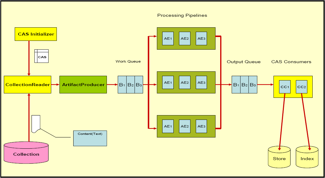
An illustration of the CPE runtime is shown in Figure 3.1, “CPE Runtime Overview”. Some of the CPE components, such as the queues and processing pipelines, are internal to the CPE, but their behavior and deployment may be configured using the CPE Descriptor. Other CPE components, such as the Collection Reader and CAS Processors, are defined and configured externally from the CPE and then plugged in to the CPE to create the overall engine. The parts of a CPE are:
- Collection Reader
understands the native data collection format and iterates over the collection producing subjects of analysis
- CAS Initializer[3]
initializes a CAS with a subject of analysis
- Artifact Producer
asynchronously pulls CASes from the Collection Reader, creates batches of CASes and puts them into the work queue
- Work Queue
shared queue containing batches of CASes queued by the Artifact Producer for analysis by Analysis Engines
- B1-Bn
individual batches containing 1 or more CASes
- AE1-AEn
Analysis Engines arranged by a CPE descriptor
- Processing Pipelines
each pipeline runs in a separate thread and contains a replicated set of the Analysis Engines running in the defined sequence
- Output Queue
holds batches of CASes with analysis results intended for CAS Consumers
- CAS Consumers
perform collection level analysis over the CASes and extract analysis results, e.g., creating indexes or databases
3.2. Notation
CPE Descriptors are XML files. This chapter uses an informal notation to specify the syntax of CPE Descriptors.
The notation used in this chapter is:
An ellipsis (...) inside an element body indicates that the substructure of that element has been omitted (to be described in another section of this chapter). An example of this would be:
<collectionReader>
...
</collectionReader>
An ellipsis immediately after an element indicates that the element type may be repeated arbitrarily many times. For example:
<parameter>[String]</parameter>
<parameter>[String]</parameter>
...
indicates that there may be arbitrarily many parameter elements in this context.
An ellipsis inside an element means details of the attributes associated with that element are defined later, e.g.:
<casProcessor ...>
Bracketed expressions (e.g.
[String]) indicate the type of value that may be used at that location.A vertical bar, as in
true|false, indicates alternatives. This can be applied to literal values, bracketed type names, and elements.
Which elements are optional and which are required is specified in prose, not in the syntax definition.
3.3. Imports
As of version 2.2, a CPE Descriptor can use the same import mechanism
as other component descriptors. This allows referring to component
descriptors using either relative paths (resolved relative to the location of the CPE descriptor)
or the classpath/datapath. For details see Chapter 2, Component Descriptor Reference.
The follwing older syntax is still supported, but not recommended:
<descriptor>
    <include href="[URL or File]"/>
</descriptor>
The [URL or File] attribute is a URL or a filename for the descriptor of the
incorporated component. The argument is first attempted to be resolved as a URL.
Relative paths in an include are resolved relative to the current working directory
(NOT the CPE descriptor location as is the case for import).
A filename relative to another directory can be specified using the CPM_HOME
variable, e.g.,
<descriptor>
    <include href="${CPM_HOME}/desc_dir/descriptor.xml"/>
</descriptor>
In this case, the value for the CPM_HOME variable must be
provided to the CPE by specifying it on the Java command line, e.g.,
java -DCPM_HOME="C:/Program Files/apache/uima/cpm" ...
3.4. CPE Descriptor Overview
A CPE Descriptor consists of information describing the following four main elements.
The Collection Reader, which is responsible for gathering artifacts and initializing the Common Analysis Structure (CAS) used to support processing in the UIMA collection processing engine.
The CAS Processors, responsible for analyzing individual artifacts, analyzing across artifacts, and extracting analysis results. CAS Processors include Analysis Engines and CAS Consumers.
Operational parameters of the Collection Processing Manager (CPM), such as checkpoint frequency and deployment mode.
Resource Manager Configuration (optional).
The CPE Descriptor has the following high level skeleton:
<?xml version="1.0"?>
<cpeDescription>
   <collectionReader>
...
   </collectionReader>
   <casProcessors>
...
   </casProcessors>
   <cpeConfig>
...
   </cpeConfig>
   <resourceManagerConfiguration>
...
   </resourceManagerConfiguration>
</cpeDescription>
Details of each of the four main elements are described in the sections that follow.
3.5. Collection Reader
The <collectionReader> section identifies the
Collection Reader and optional CAS Initializer that are to be used in the CPE. The
Collection Reader is responsible for retrieval of artifacts from a collection
outside of the CPE, and the optional CAS Initializer (deprecated as of UIMA Version 2)
is responsible for initializing the CAS with the artifact.
A Collection Reader may initialize the CAS itself, in which case it does not require a CAS Initializer. This should be clearly specified in the documentation for the Collection Reader. Specifying a CAS Initializer for a Collection Reader that does not make use of a CAS Initializer will not cause an error, but the specified CAS Initializer will not be used.
The complete structure of the <collectionReader>
section is:
<collectionReader>
  <collectionIterator>
    <descriptor>
      <import ...> | <include .../>
    </descriptor>
    <configurationParameterSettings>...</configurationParameterSettings>
    <sofaNameMappings>...</sofaNameMappings>
  </collectionIterator>
  <casInitializer>
    <descriptor>
      <import ...> | <include .../>
    </descriptor>
    <configurationParameterSettings>...</configurationParameterSettings>
    <sofaNameMappings>...</sofaNameMappings>
  </casInitializer>
</collectionReader>
The <collectionIterator> identifies the
descriptor for the Collection Reader, and the <casInitializer>
identifies the descriptor for the CAS Initializer. The format and
details of the Collection Reader and CAS Initializer descriptors are described in
Section 2.6.1, “Collection Reader Descriptors”
. The <configurationParameterSettings> and the
<sofaNameMappings> elements are described in the next
section.
3.5.1. Error handling for Collection Readers
The CPM will abort if the Collection Reader throws a large number of
consecutive exceptions (default = 100). This default can by changed by using the
Java initialization parameter -DMaxCRErrorThreshold
xxx.
3.6. CAS Processors
The <casProcessors> section identifies the
components that perform the analysis on the input data, including CAS analysis
(Analysis Engines) and analysis results extraction (CAS Consumers). The CAS
Consumers may also perform collection level analysis, where the analysis is
performed (or aggregated) over multiple CASes. The basic structure of the CAS
Processors section is:
<casProcessors
    dropCasOnException="true|false"
    casPoolSize="[Number]"
    processingUnitThreadCount="[Number]">

  <casProcessor ...>
        ...
  </casProcessor>

  <casProcessor ...>
        ...
  </casProcessor>
    ...
</casProcessors>
The <casProcessors> section has two mandatory
attributes and one optional attribute that configure the characteristics of the CAS
Processor flow in the CPE. The first mandatory attribute is a casPoolSize, which
defines the fixed number of CAS instances that the CPM will create and use during
processing. All CAS instances are maintained in a CAS Pool with a check-in and
check-out access. Each CAS is checked-out from the CAS Pool by the Collection Reader
and initialized with an initial subject of analysis. The CAS is checked-in into the
CAS Pool when it is completely processed, at the end of the processing chain. A larger
CAS Pool size will result in more memory being used by the CPM. CAS objects can be large
and care should be taken to determine the optimum size of the CAS Pool, weighing memory
tradeoffs with performance.
The second mandatory <casProcessors> attribute
is processingUnitThreadCount, which specifies the number of
replicated Processing Pipelines. Each Processing
Pipeline runs in its own thread. The CPM takes CASes from the work queue and submits
each CAS to one of the Processing Pipelines for analysis. A Processing Pipeline
contains one or more Analysis Engines invoked in a given sequence. If more than one
Processing Pipeline is specified, the CPM replicates instances of each Analysis
Engine defined in the CPE descriptor. Each Processing Pipeline thread runs
independently, consuming CASes from work queue and depositing CASes with analysis
results onto the output queue. On multiprocessor machines, multiple Processing
Pipelines can run in parallel, improving overall throughput of the CPM.
Note
The number of Processing Pipelines should be equal to or greater than CAS Pool size.
Elements in the pipeline (each represented by a <casProcessor> element) may indicate that they do not permit multiple deployment in their Analysis Engine descriptor. If so, even though multiple pipelines are being used, all CASes passing through the pipelines will be routed through one instance of these marked Engines.
The final, optional, <casProcessors> attribute is
dropCasOnException. It defines a policy that determines what
happens with the CAS when an exception happens during processing. If the value of this
attribute is set to true and an exception happens, the CPM will notify all registered
listeners of the exception (see Section 2.3.1, “Using Listeners”), clear the CAS and check the CAS
back into the CAS Pool so that it can be re-used. The presumption is that an exception
may leave the CAS in an inconsistent state and therefore that CAS should not be allowed
to move through the processing chain. When this attribute is omitted the CPM's
default is the same as specifying
dropCasOnException="false".
3.6.1. Specifying an Individual CAS Processor
The CAS Processors that make up the Processing Pipeline and the CAS Consumer
pipeline are specified with the <casProcessor>
entity, which appears within the <casProcessors>
entity. It may appear multiple times, once for each CAS Processor specified for
this CPE.
The order of the <casProcessor> entities with
the <casProcessors> section specifies the order in
which the CAS Processors will run. Although CAS Consumers are usually put at the end
of the pipeline, they need not be. Also, Aggregate Analysis Engines may include CAS
Consumers.
The overall format of the <casProcessor> entity
is:
<casProcessor deployment="local|remote|integrated" name="[String]" >
    <descriptor>
      <import ...> | <include .../>
    </descriptor>
    <configurationParameterSettings>...</configurationParameterSettings>
    <sofaNameMappings>...</sofaNameMappings>
    <runInSeparateProcess>...</runInSeparateProcess>
    <deploymentParameters>...</deploymentParameters>
    <filter/>
    <errorHandling>...</errorHandling>
    <checkpoint batch="Number"/>
</casProcessor>
The <casProcessor> element has two mandatory
attributes, deployment and name. The
mandatory name attribute specifies a unique string
identifying the CAS Processor.
The mandatory deployment attribute specifies the CAS
Processor deployment mode. Currently, three deployment options are supported:
- integrated
indicates integrated deployment of the CAS Processor. The CPM deploys and collocates the CAS Processor in the same process space as the CPM. This type of deployment is recommended to increase the performance of the CPE. However, it is NOT recommended to deploy annotators containing JNI this way. Such CAS Processors may cause a fatal exception and force the JVM to exit without cleanup (bringing down the CPM). Any UIMA SDK compliant pure Java CAS Processors may be safely deployed this way.
The descriptor for an integrated deployment can, in fact, be a remote service descriptor. When used this way, however, the CPM error recovery options (see below) operate in the integrated mode, which means that many of the retry options are not available.
- remote
indicates non-managed deployment of the CAS Processor. The CAS Processor descriptor referenced in the
<descriptor>element must be a Vinci Service Client Descriptor, which identifies a remotely deployed CAS Processor service (see Section 3.6, “Working with Remote Services”). The CPM assumes that the CAS Processor is already running as a remote service and will connect to it using the URI provided in the client service descriptor. The lifecycle of a remotely deployed CAS Processor is not managed by the CPM, so appropriate infrastructure should be in place to start/restart such CAS Processors when necessary. This deployment provides fault isolation and is implementation (i.e., programming language) neutral.- local
indicates managed deployment of the CAS Processor. The CAS Processor descriptor referenced in the
<descriptor>element must be a Vinci Service Deployment Descriptor, which configures a CAS Processor for deployment as a Vinci service (see Section 3.6, “Working with Remote Services”). The CPM deploys the CAS Processor in a separate process and manages the life cycle (start/stop) of the CAS Processor. Communication between the CPM and the CAS Processor is done with Vinci. When the CPM completes processing, the process containing the CAS Processor is terminated. This deployment mode insulates the CPM from the CAS Processor, creating a more robust deployment at the cost of a small communication overhead. On multiprocessor machines, the separate processes may run concurrently and improve overall throughput.
A number of elements may appear within the
<casProcessor> element.
3.6.1.1. <descriptor> Element
The <descriptor> element is mandatory. It
identifies the descriptor for the referenced CAS Processor using the syntax
described in Section 2.4, “Analysis Engine Descriptors”.
For
remoteCAS Processors, the referenced descriptor must be a Vinci Service Client Descriptor, which identifies a remotely deployed CAS Processor service.For local CAS Processors, the referenced descriptor must be a Vinci Service Deployment Descriptor.
For integrated CAS Processors, the referenced descriptor must be an Analysis Engine Descriptor (primitive or aggregate).
See Section 3.6, “Working with Remote Services” for more information on creating these descriptors and deploying services.
3.6.1.2. <configurationParameterSettings> Element
This element provides a way to override the contained Analysis Engine's parameters settings. Any entry specified here must already be defined; values specified replace the corresponding values for each parameter. For Cas Processors, this mechanism is only available when they are deployed in “integrated” mode. For Collection Readers and Initializers, it always is available.
The content of this element is identical to the component descriptor for specifying parameters (in the case where no parameter groups are specified)[4]. Here is an example:
<configurationParameterSettings>
  <nameValuePair>
    <name>CivilianTitles</name>
    <value>
      <array>
        <string>Mr.</string>
        <string>Ms.</string>
        <string>Mrs.</string>
        <string>Dr.</string>
      </array>
    </value>
  </nameValuePair>
  ...
</configurationParameterSettings>
3.6.1.3. <sofaNameMappings> Element
This optional element provides a mapping from defined Sofa names in the component, or the default Sofa name (if the component does not declare any Sofa names). The form of this element is:
<sofaNameMappings>
  <sofaNameMapping cpeSofaName="a_CPE_name"
                   componentSofaName="a_component_Name"/>
  ...
</sofaNameMappings>
There can be any number of
<sofaNameMapping> elements contained in the
<sofaNameMappings> element. The
componentSofaName attribute is optional; leave it out to
specify a mapping for the _InitialView - that is, for
Single-View components.
3.6.1.4. <runInSeparateProcess> Element
The <runInSeparateProcess> element is
mandatory for local CAS Processors, but should not appear
for remote or integrated CAS
Processors. It enables the CPM to create external processes using the provided
runtime environment. Applications launched this way communicate with the CPM
using the Vinci protocol and connectivity is enabled by a local instance of the
VNS that the CPM manages. Since communication is based on Vinci, the application
need not be implemented in Java. Any language for which Vinci provides support
may be used to create an application, and the CPM will seamlessly communicate
with it. The overall structure of this element is:
<runInSeparateProcess>
    <exec dir="[String]" executable="[String]">
        <env key="[String]" value ="[String]"/>
        ...
        <arg>[String]</arg>
        ...
    </exec>
</runInSeparateProcess>
The <exec> element provides information
about how to execute the referenced CAS Processor. Two attributes are defined
for the <exec> element. The
dir attribute is currently not used – it is reserved
for future functionality. The executable attribute
specifies the actual Vinci service executable that will be run by the CPM, e.g.,
java, a batch script, an application (.exe), etc. The
executable must be specified with a fully qualified path, or be found in the
PATH of the CPM.
The <exec> element has two elements within it
that define parameters used to construct the command line for executing the CAS
Processor. These elements must be listed in the order in which they should be
defined for the CAS Processor.
The optional <env> element is used to set an
environment variable. The variable key will be set to
value. For example,
<env key="CLASSPATH" value="C:Javalib"/>
will set the environment variable CLASSPATH to the value
C:Javalib. The <env>
element may be repeated to set multiple environment variables. All of the
key/value pairs will be added to the environment by the CPM prior to launching the
executable.
Note
The CPM actually adds ALL system environment variables when it launches the program. It queries the Operating System for its current system variables and one by one adds them to the program's process configuration.
The <arg> element is used to specify arbitrary
string arguments that will appear on the command line when the CPM runs the
command specified in the executable attribute.
For example, the following would be used to invoke the UIMA Java implementation of the Vinci service wrapper on a Java CAS Processor:
<runInSeparateProcess>
    <exec executable="java">
        <arg>-DVNS_HOST=localhost</arg>
        <arg>-DVNS_PORT=9099</arg>
        <arg>org.apache.uima.reference_impl.analysis_engine.service.
vinci.VinciAnalysisEngineService_impl</arg>
        <arg>C:uimadescdeployCasProcessor.xml</arg>
    </exec>
<runInSeparateProcess>
This will cause the CPM to run the following command line when starting the CAS Processor:
java -DVNS_HOST=localhost -DVNS_PORT=9099
  org.apache.uima.reference_impl.analysis_engine.service.vinci.\\
              VinciAnalysisEngineService_impl
  C:uimadescdeployCasProcessor.xml
The first argument specifies that the Vinci Naming Service is running on the
localhost. The second argument specifies that the Vinci
Naming Service port number is 9099. The third argument
(split over 2 lines in this documentation)
identifies the UIMA implementation of the Vinci service wrapper. This class
contains the main method that will execute. That main
method in turn takes a single argument – the filename for the CAS Processor
service deployment descriptor. Thus the last argument identifies the Vinci
service deployment descriptor file for the CAS Processor. Since this is the same
descriptor file specified earlier in the
<descriptor> element, the string
${descriptor} can be used to refer to the descriptor,
e.g.:
<arg>${descriptor}</arg>
The CPM will expand this out to the service deployment descriptor file
referenced in the <descriptor> element.
3.6.1.5. <deploymentParameters> Element
The <deploymentParameters> element defines
a number of deployment parameters that control how the CPM will interact with the
CAS Processor. This element has the following overall form:
<deploymentParameters>
    <parameter name="[String]" value="..." type="string|integer" />
    ...
</deploymentParameters>
The name attribute identifies the parameter, the
value attribute specifies the value that will be assigned
to the parameter, and the type attribute indicates the
type of the parameter, either string or
integer. The available parameters include:
- service-access
string parameter whose value must be “exclusive”, if present. This parameter is only effective for remote deployments. It modifies the Vinci service connections to be preallocated and dedicated, one service instance per pipe-line. It is only relevant for non-Integrated deployement modes. If there are fewer services instances that are available (and alive – responding to a “ping” request) than there are pipelines, the number of pipelines (the number of concurrent threads) is reduced to match the number of available instances. If not specified, the VNS is queried each time a service is needed, and a “random” instance is assigned from the pool of available instances. If a services dies during processing, the CPM will use its normal error handling procedures to attempt to reconnect. The number of attempts is specified in the CPE descriptor for each Cas Processor using the
<maxConsecutiveRestarts value="10"
                  action="kill-pipeline"
                  waitTimeBetweenRetries="50"/>
xml element. The “value” attribute is the number of reconnection tries; the “action” says what to do if the retries exceed the limit. The “kill-pipeline” action stops the pipeline that was associated with the failing service (other pipelines will continue to work). The CAS in process within a killed pipeline will be dropped. These events are communicated to the application using the normal event listener mechanism. ThewaitTimeBetweenRetriessays how many milliseconds to wait inbetween attempts to reconnect.- vnsHost
(Deprecated) string parameter specifying the VNS host, e.g.,
localhostfor local CAS Processors, host name or IP address of VNS host for remote CAS Processors. This parameter is deprecated; use the parameter specification instead inside the Vinci Service Client Descriptor, if needed. It is ignored for integrated and local deployments. If present, for remote deployments, it specifies the VNS Host to use, unless that is specified in the Vinci Service Client Descriptor.- vnsPort
(Deprecated) integer parameter specifying the VNS port number. This parameter is deprecated; use the parameter specification instead inside the Vinci Service Client Descriptor, if needed. It is ignored for integrated and local deployments. If present, for remote deployments, it specifies the VNS Port number to use, unless that is specified in the Vinci Service Client Descriptor.
For example, the following parameters might be used with a CAS Processor deployed in local mode:
<deploymentParameters>
  <parameter name="service-access" value="exclusive" type="string"/>
</deploymentParameters>
3.6.1.6. <filter> Element
The <filter> element is a required element but currently should be left empty. This element is reserved for future use.
3.6.1.7. <errorHandling> Element
The mandatory <errorHandling> element
defines error and restart policies for the CAS Processor. Each CAS Processor may
define different actions in the event of errors and restarts. The CPM monitors
and logs errant behaviors and attempts to recover the component based on the
policies specified in this element.
There are two kinds of faults:
One kind only occurs with non-integrated CAS Processors – this fault is either a timeout attempting to launch or connect to the non-integrated component, or some other kind of connection related exception (for instance, the network connection might timeout or get reset).
The other kind happens when the CAS Processor component (an Annotator, for example) throws any kind of exception. This kind may occur with any kind of deployment, integrated or not.
The <errorHandling> has specifications for each of these kinds of faults. The format of this element is:
<errorHandling>
  <maxConsecutiveRestarts action="continue|disable|terminate"
                           value="[Number]"/>
  <errorRateThreshold action="continue|disable|terminate" value="[Rate]"/>
  <timeout max="[Number]"/>
</errorHandling>
The mandatory <maxConsecutiveRestarts>
element applies only to faults of the first kind, and therefore, only applies to
non-integrated deployments. If such a fault occurs, a retry is attempted, up to
value="[Number]" of times. This retry resets the
connection (if one was made) and attempts to reconnect and perhaps re-launch
(see below for details). The original CAS (not a partially updated one) is sent to
the CAS Processor as part of the retry, once the deployed component has been
successfully restarted or reconnected to.
The action attribute specifies the action to take
when the threshold specified by the value="[Number]" is
exceeded. The possible actions are:
- continue
skip any further processing for this CAS by this CAS Processor, and pass the CAS to the next CAS Processor in the Pipeline.
The “restart” action is done, because it is needed for the next CAS.
If the
dropCasOnException="true", the CPM will NOT pass the CAS to the next CAS Processor in the chain. Instead, the CPM will abort processing of this CAS, release the CAS back to the CAS Pool and will process the next CAS in the queue.The counter counting the restarts toward the threshold is only reset after a CAS is successfully processed.
- disable
the current CAS is handled just as in the
continuecase, but in addition, the CAS Processor is marked so that its process() method will not be called again (i.e., it will be “skipped” for future CASes)- terminate
the CPM will terminate all processing and exit.
The definition of an error for the
<maxConsecutiveRestarts> element differs
slightly for each of the three CAS Processor deployment modes:
- local
Local CAS Processors experience two general error types:
launch errors – errors associated with launching a process
processing errors – errors associated with sending Vinci commands to the process
A launch error is defined by a failure of the process to successfully register with the local VNS within a default time window. The current timeout is 15 minutes. Multiple local CAS Processors are launched sequentially, with a subsequent processor launched immediately after its previous processor successfully registers with the VNS.
A processing error is detected if a connection to the CAS Processor is lost or if the processing time exceeds a specified timeout value.
For local CAS Processors, the <maxConsecutiveRestarts> element specifies the number of consecutive attempts made to launch the CAS Processor at CPM startup or after the CPM has lost a connection to the CAS Processor.
- remote
For remote CAS Processors, the <maxConsecutiveRestarts> element applies to errors from sending Vinci commands. An error is detected if a connection to the CAS Processor is lost, or if the processing time exceeds the timeout value specified in the <timeout> element (see below).
- integrated
Although mandatory, the <maxConsecutiveRestarts> element is NOT used for integrated CAS Processors, because Integrated CAS Processors are not re-instantiated/restarted on exceptions. This setting is ignored by the CPM for Integrated CAS Processors but it is required. Future version of the CPM will make this element mandatory for remote and local CAS Processors only.
The mandatory <errorRateThreshold> element
is used for all faults – both those above, and exceptions thrown by the CAS
Processor itself. It specifies the number of retries for exceptions thrown by
the CAS Processor itself, a maximum error rate, and the corresponding action to
take when this rate is exceeded. The value attribute
specifies the error rate in terms of errors per sample size in the form
“N/M”, where N is the
number of errors and M is the sample size, defined in terms
of the number of documents.
The first number is used also to indicate the maximum number of retries. If
this number is less than the <maxConsecutiveRestarts
value="[Number]">, it will override, reducing the number of
“restarts” attempted. A retry is done only if the
dropCasOnException is false. If it is set to true, no retry
occurs, but the error is counted.
When the number of counted errors exceeds the sample size, an action
specified by the action attribute is taken. The possible
actions and their meaning are the same as described above for the
<maxConsecutiveRestarts> element:
continuedisableterminate
The dropCasOnException="true" attribute of the
<casProcessors> element modifies the action
taken for continue and disable, in the same manner as above. For example:
<errorRateThreshold value="3/1000" action="disable"/>
specifies that each error thrown by the CAS Processor itself will be retried up to
3 times (if dropCasOnException is false) and the CAS
Processor will be disabled if the error rate exceeds 3 errors in 1000
documents.
If a document causes an error and the error rate threshold for the CAS
Processor is not exceeded, the CPM increments the CAS Processor's error
count and retries processing that document (if
dropCasOnException is false). The retry means that the
CPM calls the CAS Processor's process() method again, passing in as an
argument the same CAS that previously caused an exception.
Note
The CPM does not attempt to rollback any partial changes that may have been applied to the CAS in the previous process() call.
Errors are accumulated across documents. For example, assume the error
rate threshold is 3/1000. The same document may fail three
times before finally succeeding on the fourth try, but the error count is now 3. If
one more error occurs within the current sample of 1000 documents, the error rate
threshold will be exceeded and the specified action will be taken. If no more
errors occur within the current sample, the error counter is reset to 0 for the
next sample of 1000 documents.
The <timeout> element is a mandatory element.
Although mandatory for all CAS Processors, this element is only relevant for
local and remote CAS Processors. For integrated CAS Processors, this element is
ignored. In the current CPM implementation the integrated CAS Processor
process() method is not subject to timeouts.
The max attribute specifies the maximum amount of
time in milliseconds the CPM will wait for a process() method to complete When
exceeded, the CPM will generate an exception and will treat this as an error
subject to the threshold defined in the
<errorRateThreshold> element above, including
doing retries.
Retry action taken on a timeout
The action taken depends on whether the CAS Processor is local (managed) or remote (unmanaged). Local CAS Processors (which are services) are killed and restarted, and a new connection to them is established. For remote CAS Processors, the connection to them is dropped, and a new connection is reestablished (which may actually connect to a different instance of the remote services, if it has multiple instances).
3.6.1.8. <checkpoint> Element
The <checkpoint> element is an optional
element used to improve the performance of CAS Consumers. It has a single
attribute, batch, which specifies the number of CASes in a
batch, e.g.:
<checkpoint batch="1000">
sets the batch size to 1000 CASes. The batch size is the interval used to mark a
point in processing requiring special handling. The CAS Processor's
batchProcessComplete() method will be called by the CPM
when this mark is reached so that the processor can take appropriate action. This
mark could be used as a mechanism to buffer up results in CAS Consumers and perform
time-consuming operations, such as check-pointing, that should not be done on a
per-document basis.
3.7. CPE Operational Parameters
The parameters for configuring the overall CPE and CPM are specified in the
<cpeConfig> section. The overall format of this
section is:
<cpeConfig>
  <startAt>[NumberOrID]</startAt>

  <numToProcess>[Number]</numToProcess>

  <outputQueue dequeueTimeout="[Number]" queueClass="[ClassName]" />

  <checkpoint file="[File]" time="[Number]" batch="[Number]"/>

  <timerImpl>[ClassName]</timerImpl>

  <deployAs>vinciService|interactive|immediate|single-threaded
  </deployAs>

</cpeConfig>
This section of the CPE descriptor allows for defining the starting entity, the number of entities to process, a checkpoint file and frequency, a pluggable timer, an optional output queue implementation, and finally a mode of operation. The mode of operation determines how the CPM interacts with users and other systems.
The <startAt> element is an optional argument. It
defines the starting entity in the collection at which the CPM should start
processing.
The implementation in the CPM passes this argument to the Collection Reader
as the value of the parameter “startNumber”.
The CPM does not do anything else with this parameter; in particular, the CPM has no
ability to skip to a specific document - that function, if available, is only provided
by a particular Collection Reader implementation.
If the <startAt> element is used, the Collection
Reader descriptor must define a single-valued configuration parameter with the
name startNumber. It can declare this value to be of any type;
the value passed in this XML element must be convertible to that type.
A typical use is to declare this to be an integer type, and to pass the sequential document number where processing should start. An alternative implementation might take a specific document ID; the collection reader could search through its collection until it reaches this ID and then start there.
This parameter will only make sense if the particular collection reader is
implemented to use the startNumber configuration
parameter.
The <numToProcess> element is an optional
element. It specifies the total number of entities to process. Use -1 to indicate ALL.
If not defined, the number of entities to process will be taken from the Collection
Reader configuration. If present, this value overrides the Collection Reader
configuration.
The <outputQueue> element is an optional element.
It enables plugging in a custom implementation for the Output Queue. When omitted,
the CPM will use a default output queue that is based on First-in First-out (FIFO)
model.
The UIMA SDK provides a second implementation for the Output Queue that can be
plugged in to the CPM, named “
org.apache.uima.collection.impl.cpm.engine.SequencedQueue
”.
This implementation supports handling very large documents that are split into
“chunks”; it provides a delivery mechanism that insures the
sequential order of the chunks using information carried in the CAS metadata. This
metadata, which is required for this implementation to work correctly, must be added
as an instance of a Feature Structure of type
org.apache.es.tt.DocumentMetaData and referred to by an
additional feature named esDocumentMetaData in the special
instance of uima.tcas.DocumentAnnotation that is
associated with the CAS. This is usually done by the Collection Reader; the instance
contains the following features:
- sequenceNumber
[Number] the sequential number of a chunk, starting at 1. If not a chunk (i.e. complete document), the value should be 0.
- documentId
[Number] current document id. Chunks belonging to the same document have identical document id.
- isCompleted
[Number] 1 if the chunk is the last in a sequence, 0 otherwise.
- url
[String] document url.
- throttleID
[String] special attribute currently used by OmniFind.
This implementation of a sequenced queue supports proper sequencing of CASes in CPM deployments that use document chunking. Chunking is a technique of splitting large documents into pieces to reduce overall memory consumption. Chunking does not depend on the number of CASes in the CAS Pool. It works equally well with one or more CASes in the CAS Pool. Each chunk is packaged in a separate CAS and placed in the Work Queue. If the CAS Pool is depleted, the CollectionReader thread is suspended until a CAS is released back to the pool by the processing threads. A document may be split into 1, 2, 3 or more chunks that are analyzed independently. In order to reconstruct the document correctly, the CAS Consumer can depend on receiving the chunks in the same sequential order that the chunks were “produced”, when this sequenced queue implementation is used. To plug in this sequenced queue to the CPM use the following specification:
<outputQueue dequeueTimeout="100000" queueClass=
"org.apache.uima.collection.impl.cpm.engine.SequencedQueue"/>
where the mandatory queueClass attribute defines the name of
the class and the second mandatory attribute, dequeueTimeout
specifies the maximum number of milliseconds to wait for the expected chunk.
Note
The value for this timeout must be carefully determined to avoid excessive occurrences of timeouts. Typically, the size of a chunk and the type of analysis being done are the most important factors when deciding on the value for the timeout. The larger the chunk and the more complicated analysis, the more time it takes for the chunk to go from source to sink. You may specify 0, in which case, the timeout is disabled - i.e., it is equivalent to an infinitely long timeout.
If the chunk doesn't arrive in the configured time window, the entire document is presumed to be invalid and the CAS is dropped from further processing. This action occurs regardless of any other error action specification. The SequencedQueue invalidate the document, adding the offending document's metadata to a local cache of invalid documents.
If the time out occurs, the CPM notifies all registered listeners (see Section 2.3.1, “Using Listeners”) by calling entityProcessComplete(). As part of this call, the SequencedQueue will pass null instead of a CAS as the first argument, and a special exception – CPMChunkTimeoutException. The reason for passing null as the first argument is because the time out occurs due to the fact that the chunk has not been received in the configured timeout window, so there is no CAS available when the timeout event occurs.
The CPMChunkTimeoutException object includes an API that allows the listener to retrieve the offending document id as well as the other metadata attributes as defined above. These attributes are part of each chunk's metadata and are added by the Collection Reader.
Each chunk that SequencedQueue works on is subjected to a test to determine if the chunk belongs to an invalid document. This test checks the chunk's metadata against the data in the local cache. If there is a match, the chunk is dropped. This check is only performed for chunks and complete documents are not subject to this check.
If there is an exception during the processing of a chunk, the CPM sends a notification to all registered listeners. The notification includes the CAS and an exception. When the listener notification is completed, the CPM also sends separate notifications, containing the CAS, to the Artifact Producer and the SequencedQueue. The intent is to stop adding new chunks to the Work Queue that belong to an “invalid” document and also to deal with chunks that are en-route, being processed by the processing threads.
In response to the notification, the Artifact Producer will drop and release back to the CAS Pool all CASes that belong to an “invalid” document. Currently, there is no support in the CollectionReader's API to tell it to stop generating chunks. The CollectionReader keeps producing the chunks but the Artifact Producer immediately drops/releases them to the CAS Pool. Before the CAS is released back to the CAS Pool, the Artifact Producer sends notification to all registered listeners. This notification includes the CAS and an exception – SkipCasException.
In response to the notification of an exception involving a chunk, the SequencedQueue retrieves from the CAS the metadata and adds it to its local cache of “invalid” documents. All chunks de-queued from the OutputQueue and belonging to “invalid” documents will be dropped and released back to the CAS Pool. Before dropping the CAS, the CPM sends notification to all registered listeners. The notification includes the CAS and SkipCasException.
The <checkpoint> element is an optional element.
It specifies a CPE checkpoint file, checkpoint frequency, and strategy for
checkpoints (time or count based). At checkpoint time, the CPM saves status
information and statistics to the checkpoint file. The checkpoint file is specified
in the file attribute, which has the same form as the
href attribute of the <include>
element described in Section 3.3, “Imports”. The
time attribute indicates that a checkpoint should be taken
every [Number] seconds, and the batch
attribute indicates that a checkpoint should be taken every
[Number] batches.
The <timerImpl> element is optional. It is used to
identify a custom timer plug-in class to generate time stamps during the CPM
execution. The value of the element is a Java class name.
The <deployAs> element indicates the type of CPM
deployment. Valid contents for this element include:
- vinciService
Vinci service exposing APIs for stop, pause, resume, and getStats
- interactive
provide command line menus (start, stop, pause, resume)
- immediate
run the CPM without menus or a service API
- single-threaded
run the CPM in a single threaded mode. In this mode, the Collection Reader, the Processing Pipeline, and the CAS Consumer Pipeline are all running in one thread without the work queue and the output queue.
3.8. Resource Manager Configuration
External resource bindings for the CPE may optionally be specified in an element:
<resourceManagerConfiguration href="..."/>
For an introduction to external resources, refer to Section 1.5.4, “Accessing External Resources”.
In the resourceManagerConfiguration element, the value
of the href attribute refers to another file that contains definitions and bindings
for the external resources used by the CPE. The format of this file is the same as the XML
snippet Section 2.4.2.5, “External Resource Bindings”
. For example, in a CPE containing an aggregate analysis engine with two annotators,
and a CAS Consumer, the following resource manager configuration file would bind
external resource dependencies in all three components to the same physical
resource:
<resourceManagerConfiguration>

  <!-- Declare Resource -->

  <externalResources>
    <externalResource>
      <name>ExampleResource</name>
      <fileResourceSpecifier>
        <fileUrl>file:MyResourceFile.dat</fileUrl>
      </fileResourceSpecifier>
    </externalResource>
  </externalResources>

  <!-- Bind component resource dependencies to ExampleResource -->

  <externalResourceBindings>
    <externalResourceBinding>
      <key>MyAE/annotator1/myResourceKey</key>
      <resourceName>ExampleResource</resourceName>
    </externalResourceBinding>

    <externalResourceBinding>
      <key>MyAE/annotator2/someResourceKey</key>
      <resourceName>ExampleResource</resourceName>
    </externalResourceBinding>

    <externalResourceBinding>
      <key>MyCasConsumer/otherResourceKey</key>
      <resourceName>ExampleResource</resourceName>
    </externalResourceBinding>

  </externalResourceBindings>

</resourceManagerConfiguration>
In this example, MyAE and
MyCasConsumer are the names of the Analysis Engine and CAS
Consumer, as specified by the name attributes of the CPE's
<casProcessor> elements.
annotator1 and annotator2 are the
annotator keys specified within the Aggregate AE Descriptor, and
myResourceKey, someResourceKey, and
otherResourceKey are the keys of the resource dependencies
declared in the individual annotator and CAS Consumer descriptors.
3.9. Example CPE Descriptor
<?xml version="1.0" encoding="UTF-8"?>
<cpeDescription>
  <collectionReader>
    <collectionIterator>
      <descriptor>
        <import location=
           "../collection_reader/FileSystemCollectionReader.xml"/>
      </descriptor>
    </collectionIterator>
  </collectionReader>
  <casProcessors dropCasOnException="true" casPoolSize="1"
      processingUnitThreadCount="1">
    <casProcessor deployment="integrated"
      name="Aggregate TAE - Name Recognizer and Person Title Annotator">
      <descriptor>
        <import location=
           "../analysis_engine/NamesAndPersonTitles_TAE.xml"/>
      </descriptor>
      <deploymentParameters/>
      <filter/>
      <errorHandling>
        <errorRateThreshold action="terminate" value="100/1000"/>
                <maxConsecutiveRestarts action="terminate" value="30"/>
                <timeout max="100000"/>
      </errorHandling>
      <checkpoint batch="1"/>
    </casProcessor>
    <casProcessor deployment="integrated" name="Annotation Printer">
      <descriptor>
        <import location="../cas_consumer/AnnotationPrinter.xml"/>
      </descriptor>
      <deploymentParameters/>
      <filter/>
      <errorHandling>
        <errorRateThreshold action="terminate" value="100/1000"/>
        <maxConsecutiveRestarts action="terminate" value="30"/>
        <timeout max="100000"/>
      </errorHandling>
      <checkpoint batch="1"/>
    </casProcessor>
  </casProcessors>
  <cpeConfig>
    <numToProcess>1</numToProcess>
    <deployAs>immediate</deployAs>
    <checkpoint file="" time="3000"/>
    <timerImpl/>
  </cpeConfig>
</cpeDescription>
Chapter 4. CAS Reference
The CAS (Common Analysis System) is the part of the Unstructured Information Management Architecture (UIMA) that is concerned with creating and handling the data that annotators manipulate.
Java users typically use the JCas (Java interface to the CAS) when manipulating objects in the CAS. This chapter describes an alternative interface to the CAS which allows discovery and specification of types and features at run time. It is recommended for use when the using code cannot know ahead of time the type system it will be dealing with.
Use of the CAS as described here is also recommended (or necessary) when components add to the definitions of types of other components. This UIMA feature allows users to add features to a type that was already defined elsewhere. When this feature is used in conjunction with the JCas, it can lead to problems with class loading. This is because different JCas representations of a single type are generated by the different components, and only one of them is loaded (unless you are using Pear descriptors). Note: we do not recommend that you add features to pre-existing types. A type should be defined in one place only, and then there is no problem with using the JCas. However, if you do use this feature, do not use the JCas. Similarly, if you distribute your components for inclusion in somebody else's UIMA application, and you're not sure that they won't add features to your types, do not use the JCas for the same reasons.
CASes passed to Annotator Components are either a base CAS or a regular CAS. Base CASes are only passed to Multi-View components - they are like regular CASes, but do not have user accessible indexes or Sofas. They are used by the component only for switching to other CAS views, which are regular CASes.
4.1. Javadocs
The subdirectory docs/api contains the documentation
details of all the classes, methods, and constants for the APIs discussed here. Please
refer to this for details on the methods, classes and constants, specifically in the
packages org.apache.uima.cas.*.
4.2. CAS Overview
There are three[5] main parts to the CAS: the type system, data creation and manipulation, and indexing. We will start with a brief description of these components.
4.2.1. The Type System
The type system specifies what kind of data you will be able to manipulate in your annotators. The type system defines two kinds of entities, types and features. Types are arranged in a single inheritance tree and define the kinds of entities (objects) you can manipulate in the CAS. Features optionally specify slots or fields within a type. The correspondence to Java is to equate a CAS Type to a Java Class, and the CAS Features to fields within the type. A critical difference is that CAS types have no methods; they are just data structures with named slots (features). These features can have as values primitive things like integers, floating point numbers, and strings, and they also can hold references to other instances of objects in the CAS. We call instances of the data structures declared by the type system “feature structures” (not to be confused with “features”). Feature structures are similar to the many variants of record structures found in computer science.[6]
Each CAS Type defines a supertype; it is a subtype of that supertype. This means that any features that the supertype defines are features of the subtype; in other words, it inherits its supertype's features. Only single inheritance is supported; a type's feature set is the union of all of the features in its supertype hierarchy. There is a built-in type called uima.cas.TOP; this is the top, root node of the inheritance tree. It defines no features.
The values that can be stored in features are either built-in primitive values or
references to other feature structures. The primitive values are
boolean, byte,
short (16 bit integers), integer (32
bit), long (64 bit), float (32 bit),
double (64 bit floats) and strings; the official names of these
are uima.cas.Boolean, uima.cas.Byte,
uima.cas.Short, uima.cas.Integer,
uima.cas.Long, uima.cas.Float
, uima.cas.Double and uima.cas.String
. The strings are Java strings, and characters are Java characters. Technically, this means
that characters are UTF-16 code points, which is not quite the same as a Unicode character.
This distinction should make no difference for almost all applications.
The CAS also defines other basic built-in types for arrays of these, plus arrays of
references to other objects, called uima.cas.IntegerArray
, uima.cas.FloatArray,
uima.cas.StringArray,
uima.cas.FSArray, etc.
The CAS also defines a built-in type called
uima.tcas.Annotation which inherits from
uima.cas.AnnotationBase which in turn inherits from
uima.cas.TOP. There are two features defined by this type,
called begin and end, both of which are
integer valued.
4.2.2. Creating, accessing and manipulating data
Creating and accessing data in the CAS requires knowledge about the types and features
defined in the type system. The idea is similar to other data access APIs, such as the XML
DOM or SAX APIs, or database access APIs such as JDBC. Contrary to those APIs, however, the
CAS does not use the names of type system entities directly in the APIs. Rather, you use
the type system to access type and feature entities by name, then use these entities in the
data manipulation APIs. This can be compared to the Java reflection APIs: the type system
is comparable to the Java class loader, and the type and feature objects to the
java.lang.Class and java.lang.reflect.Field classes.
Why does it have to be this complicated? You wouldn't normally use reflection to create a Java object, either. As mentioned earlier, the JCas provides the more straightforward method to manipulate CAS data. The CAS access methods described here need only be used for generic types of applications that need to be able to handle any kind of data (e.g., generic tooling) or when the JCas may not be used for other reasons. The generic kinds of applications are exactly the ones where you would use the reflection API in Java as well.
4.2.3. Creating and using indexes
Each view of a CAS provides a set of indexes for that view. Instances of feature
structures can be added to a view's indexes. These indexes provide
the only way for other annotators to locate existing data in the CAS. The only way for an
annotator to use data that another annotator has created is by using an index (or the
method getAllIndexedFS of the object FSIndexRepository) to
retrieve feature structures the first annotator created. If you want the data you
create to be visible to other annotators, you must explicitly call methods which
add it to the indexes — you must index it.
Indexes are named and are associated with a CAS Type; they are used to index instances of that CAS type (including instances of that type's subtypes). If you are using multiple views (see Chapter 6, Multiple CAS Views of an Artifact), each view contains a separate instantiation of all of the indexes. To access an index, you minimally need to know its name. A CAS view provides an index repository which you can query for indexes for that view. Once you have a handle to an index, you can get information about the feature structures in the index, the size of the index, as well as an iterator over the feature structures.
Indexes are defined in the XML descriptor metadata for the application. Each CAS View has its own, separate instantiation of indexes based on these definitions, kept in the view's index repository. When you obtain an index, it is always from a particular CAS view. When you index an item, it is always added to all indexes where it belongs, within just one repository. You can specify different repositories (associated with different CAS views) to use; a given Feature Structure instance may be indexed in more than one CAS View.
Iterators allow you to enumerate the feature structures in an index. FS iterators
provide two kinds of APIs: the regular Java iterator API, and a specific FS iterator API
where the usual Java iterator APIs (hasNext() and next())
are replaced by isValid(), moveToNext() (which does
not return an element) and get(). Which API style you use is up to you,
but we do not recommend mixing the styles as the results are sometimes unexpected. If you
just want to iterate over an index from start to finish, either style is equally appropriate.
If you also use moveTo(FeatureStructure fs) and
moveToPrevious(), it is better to use the special FS iterator style.
Note
The reason to not mix these styles is that you might be thinking that next() followed by moveToPrevious() would always work. This is not true, because next() returns the "current" element, and advances to the next position, which might be beyond the last element. At that point, the interator becomes "invalid", and by the iterator contracts, moveToNext and moveToPrevious are not allowed on "invalid" iterators; when an iterator is not valid, all bets are off. But you can call these methods on the iterator — moveToFirst(), moveToLast(), or moveTo(FS) — to reset it.
Indexes are created by specifying them in the annotator's or aggregate's resource descriptor. An index specification includes its name, the CAS type being indexed, the kind of index it is, and an (optional) ordering relation on the feature structures to be indexed. At startup time, all index specifications are combined; duplicate definitions (having the same name) are allowed only if their definitions are the same.
Feature structure instances need to be explicitly added to the index repository by a method call. Feature structures that are not indexed will not be visible to other annotators, (unless they are located via being referenced by some other feature of another feature structure, which is indexed, or through a chain of these).
The framework defines an unnamed bag index which indexes all types. The only access provided for this index is the getAllIndexedFS(type) method on the index repository, which returns an iterator over all indexed instances of the specified type (including its subtypes) for that CAS View.
The framework defines one standard, built-in annotation index, called
AnnotationIndex, which indexes the uima.tcas.Annotation
type: all feature structures of type uima.tcas.Annotation or
its subtypes are automatically indexed with this built-in index.
The ordering relation used by this index is to first order by the value of the “begin” features (in ascending order) and then by the value of the “end” feature (in descending order). This ordering insures that longer annotations starting at the same spot come before shorter ones. For Subjects of Analysis other than Text, this may not be an appropriate index.
4.3. Built-in CAS Types
The CAS has two kinds of built-in types – primitive and non-primitive. The primitive types are:
uima.cas.Boolean
uima.cas.Byte
uima.cas.Short
uima.cas.Integer
uima.cas.Long
uima.cas.Float
uima.cas.Double
uima.cas.String
The Byte, Short, Integer, and Long are
all signed integer types, of length 8, 16, 32, and 64 bits. The
Double type is 64 bit floating point. The
String type can be subtyped to create sets of allowed values; see
Section 2.3.4, “String Subtypes”.
These types can be used to specify the range of a String-valued feature. They act like
Strings, but have additional checking to insure the setting of values into them
conforms to one of the allowed values, or to null (which is the value if it is not set).
Note that the other primitive types cannot be used
as a supertype for another type definition; only
uima.cas.String can be sub-typed.
The non-primitive types exist in a type hierarchy; the top of the hierarchy is the
type uima.cas.TOP. All other non-primitive types inherit from
some supertype.
There are 9 built-in array types. These arrays have a size specified when they are created; the size is fixed at creation time. They are named:
uima.cas.BooleanArray
uima.cas.ByteArray
uima.cas.ShortArray
uima.cas.IntegerArray
uima.cas.LongArray
uima.cas.FloatArray
uima.cas.DoubleArray
uima.cas.StringArray
uima.cas.FSArray
The uima.cas.FSArray type is an array whose elements are
arbitrary other feature structures (instances of non-primitive types).
There are 3 built-in types associated with the artifact being analyzed:
uima.cas.AnnotationBase
uima.tcas.Annotation
uima.tcas.DocumentAnnotation
The AnnotationBase type defines one system-used feature
which specifies for an annotation the subject of analysis (Sofa) to which it refers. The
Annotation type extends from this and defines 2 features, taking
uima.cas.Integer values, called begin
and end. The begin feature typically
identifies the start of a span of text the annotation covers; the
end feature identifies the end. The values refer to character
offsets; the starting index is 0. An annotation of the word “CAS” in a text
“CAS Reference” would have a start index of 0, and an end index of 3; the
difference between end and start is the length of the span the annotation refers
to.
Annotations are always with respect to some Sofa (Subject of Analysis – see Chapter 5, Annotations, Artifacts, and Sofas .
Note
Artifacts which are not text strings may have a different interpretation of
the meaning of begin and end, or may define their own kind of annotation, extending from
AnnotationBase.
The DocumentAnnotation type has one special instance. It is
a subtype of the Annotation type, and the built-in definition defines one feature,
language, which is a string indicating the language of the
document in the CAS. The value of this language feature is used by the system to control
flow among annotators when the “CapabilityLanguageFlow” mode is used,
allowing the flow to skip over annotators that don't process particular
languages. Users may extend this type by adding additional features to it, using the XML
Descriptor element for defining a type.
Note
We do not recommend extending the DocumentAnnotation
type. If you do, you must not use the JCas, for the reasons stated
earlier.
Each CAS view has a different associated instance of the
DocumentAnnotation type. On the CAS, use
getDocumentationAnnotation() to access the
DocumentAnnotation.
There are also built-in types supporting linked lists, similar to the ones available in Java and other programming languages. Their use is constrained by the usual properties of linked lists: not very space efficient, no (efficient) random access, but an easy choice if you don't know how long your list will be ahead of time. The implementation is type specific; there are different list building objects for each of the primitive types, plus one for general feature structures. Here are the type names:
uima.cas.FloatList
uima.cas.IntegerList
uima.cas.StringList
uima.cas.FSList
uima.cas.EmptyFloatList
uima.cas.EmptyIntegerList
uima.cas.EmptyStringList
uima.cas.EmptyFSList
uima.cas.NonEmptyFloatList
uima.cas.NonEmptyIntegerList
uima.cas.NonEmptyStringList
uima.cas.NonEmptyFSList
For the primitive types Float,
Integer, String and
FeatureStructure, there is a base type, for instance,
uima.cas.FloatList. For each of these, there are two subtypes,
corresponding to a non-empty element, and a marker that serves to indicate the end of the
list, or an empty list. The non-empty types define two features –
head and tail. The head feature holds the
particular value for that part of the list. The tail refers to the next list object
(either a non-empty one or the empty version to indicate the end of the list).
There are no other built-in types. Users are free to define their own type systems, building upon these types.
4.4. Accessing the type system
During annotator processing, or outside an annotator, access the type system by calling
CAS.getTypeSystem().
However, CAS annotators implement an additional method,
typeSystemInit(), which is called by the UIMA framework before the
annotator's process method. This method, implemented by the annotator writer,
is passed a reference to the CAS's type system metadata. The method typically uses
the type system APIs to obtain type and feature objects corresponding to all the types
and features the annotator will be using in its process method. This initialization
step should not be done during an annotator's initialize method since the type
system can change after the initialize method is called; it should not be done during the
process method, since this is presumably work that is identical for each incoming
document, and so should be performed only when the type system changes (which will be a
rare event). The UIMA framework guarantees it will call the typeSystemInit
method of an annotator whenever the type system changes, before calling the
annotator's process() method.
The initialization done by typeSystemInit() is done by the
UIMA framework when you use the JCas APIs; you only need to provide a
typeSystemInit() method, as described here, when you are not using
the JCas approach.
4.4.1. TypeSystemPrinter example
Here is a code fragment that, given a CAS Type System, will print a list of all types.
// Get all type names from the type system
// and print them to stdout.
private void listTypes1(TypeSystem ts) {
  // Get an iterator over types
  Iterator typeIterator = ts.getTypeIterator();
  Type t;
  System.out.println("Types in the type system:");
  while (typeIterator.hasNext()) {
    // Retrieve a type...
    t = (Type) typeIterator.next();
    // ...and print its name.
    System.out.println(t.getName());
  }
  System.out.println();
}
This method is passed the type system as a parameter. From the type system, we can get an iterator over all known types. If you run this against a CAS created with no additional user-defined types, we should see something like this on the console:
Types in the type system:
uima.cas.Boolean
uima.cas.Byte
uima.cas.Short
uima.cas.Integer
uima.cas.Long
uima.cas.ArrayBase
...
If the type system had user-defined types these would show up too. Note that some of these types are not directly creatable – they are types used by the framework in the type hierarchy (e.g. uima.cas.ArrayBase).
CAS type names include a name-space prefix. The components of a type name are separated by the dot (.). A type name component must start with a Unicode letter, followed by an arbitrary sequence of letters, digits and the underscore (_). By convention, the last component of a type name starts with an uppercase letter, the rest start with a lowercase letter.
Listing the type names is mildly useful, but it would be even better if we could see the inheritance relation between the types. The following code prints the inheritance tree in indented format.
private static final int INDENT = 2;
private void listTypes2(TypeSystem ts) {
  // Get the root of the inheritance tree.
  Type top = ts.getTopType();
  // Recursively print the tree.
  printInheritanceTree(ts, top, 0);
}

private void printInheritanceTree(TypeSystem ts, Type type, int level) {
  indent(level); // Print indentation.
  System.out.println(type.getName());
  // Get a vector of the immediate subtypes.
  Vector subTypes =
    ts.getDirectlySubsumedTypes(type);
  ++level; // Increase the indentation level.
  for (int i = 0; i < subTypes.size(); i++) {
    // Print the subtypes.
    printInheritanceTree(ts, (Type) subTypes.get(i), level);
  }
}

// A simple, inefficient indenter
private void indent(int level) {
  int spaces = level * INDENT;
  for (int i = 0; i < spaces; i++) {
    System.out.print(" ");
  }
}
This example shows that you can traverse the type hierarchy by starting at the top
with TypeSystem.getTopType and by retrieving subtypes with
TypeSystem.getDirectlySubsumedTypes().
The Javadocs also have APIs that allow you to access the features, as well as what the allowed value type is for that feature. Here is sample code which prints out all the features of all the types, together with the allowed value types (the feature “range”). Each feature has a “domain” which is the type where it is defined, as well as a “range”.
private void listFeatures2(TypeSystem ts) {
  Iterator featureIterator = ts.getFeatures();
  Feature f;
  System.out.println("Features in the type system:");
  while (featureIterator.hasNext()) {
    f = (Feature) featureIterator.next();
    System.out.println(
      f.getShortName() + ": " +
      f.getDomain() + " -> " + f.getRange());
  }
  System.out.println();
}
We can ask a feature object for its domain (the type it is defined on) and its range (the type of the value of the feature). The terminology derives from the fact that features can be viewed as functions on subspaces of the object space.
4.4.2. Using the CAS APIs to create and modify feature structures
Assume a type system declaration that defines two types: Entity and Person. Entity has no features defined within it but inherits from uima.tcas.Annotation – so it has the begin and end features. Person is, in turn, a subtype of Entity, and adds firstName and lastName features. CAS type systems are declaratively specified using XML; the format of this XML is described in Section 2.3, “Type System Descriptors”.
<!-- Type System Definition -->
<typeSystemDescription>
  <types>
    <typeDescription>
      <name>com.xyz.proj.Entity</name>
      <description />
      <supertypeName>uima.tcas.Annotation</supertypeName>
    </typeDescription>
    <typeDescription>
      <name>Person</name>
      <description />
      <supertypeName>com.xyz.proj.Entity </supertypeName>
      <features>
        <featureDescription>
          <name>firstName</name>
          <description />
          <rangeTypeName>uima.cas.String</rangeTypeName>
        </featureDescription>
        <featureDescription>
          <name>lastName</name>
          <description />
          <rangeTypeName>uima.cas.String</rangeTypeName>
        </featureDescription>
      </features>
    </typeDescription>
  </types>
</typeSystemDescription>
To be able to access types and features, we need to know their names. The CAS interface defines
constants that hold the names of built-in feature names, such as, e.g.,
CAS.TYPE_NAME_INTEGER. It is good programming practice to create such
constants for the types and features you define, for your own use as well as for others who will
be using your annotators.
/** Entity type name constant. */
public static final String ENTITY_TYPE_NAME = "com.xyz.proj.Entity";

/** Person type name constant. */
public static final String PERSON_TYPE_NAME = "com. xyz.proj.Person";

/** First name feature name constant. */
public static final String FIRST_NAME_FEAT_NAME = "firstName";

/** Last name feature name constant. */
public static final String LAST_NAME_FEAT_NAME = "lastName";
Next we define type and feature member variables; these will hold the values of the
type and feature objects needed by the CAS APIs, to be assigned during
typeSystemInit().
// Type system object variables
private Type entityType;
private Type personType;
private Feature firstNameFeature;
private Feature lastNameFeature;
private Type stringType;
The type system does not throw an exception if we ask for something that is not known, it simply returns null; therefore the code checks for this and throws a proper exception. We require all these types and features to be defined for the annotator to work. One might imagine situations where certain computations are predicated on some type or feature being defined in the type system, but that is not the case here.
// Get a type object corresponding to a name.
// If it doesn't exist, throw an exception.
private Type initType(String typeName)
  throws AnnotatorInitializationException {
  Type type = ts.getType(typeName);
  if (type == null) {
    throw new AnnotatorInitializationException(
      AnnotatorInitializationException.TYPE_NOT_FOUND,
      new Object[] { this.getClass().getName(), typeName });
  }
  return type;
}

// We add similar code for retrieving feature objects.
// Get a feature object from a name and a type object.
// If it doesn't exist, throw an exception.
private Feature initFeature(String featName, Type type)
  throws AnnotatorInitializationException {
  Feature feat = type.getFeatureByBaseName(featName);
  if (feat == null) {
    throw new AnnotatorInitializationException(
      AnnotatorInitializationException.FEATURE_NOT_FOUND,
      new Object[] { this.getClass().getName(), featName });
  }
  return feat;
}
Using these two functions, code for initializing the type system described above would be:
public void typeSystemInit(TypeSystem aTypeSystem)
    throws AnalysisEngineProcessException {
  this.typeSystem = aTypeSystem;
  // Set type system member variables.
  this.entityType = initType(ENTITY_TYPE_NAME);
  this.personType = initType(PERSON_TYPE_NAME);
  this.firstNameFeature =
    initFeature(FIRST_NAME_FEAT_NAME, personType);
  this.lastNameFeature =
    initFeature(LAST_NAME_FEAT_NAME, personType);
  this.stringType = initType(CAS.TYPE_NAME_STRING);
}
Note that we initialize the string type by using a type name constant from the CAS.
4.5. Creating feature structures
To create feature structures in JCas, we use the Java “new”
operator. In the CAS, we use one of several different API methods on the CAS object,
depending on which of the 10 basic kinds of feature structures we are creating (a plain
feature structure, or an instance of the built-in primitive type arrays or FSArray).
There are is also a method to create an instance of a
uima.tcas.Annotation, setting the begin and end
values.
Once a feature structure is created, it needs to be added to the CAS indexes (unless it will be accessed via some reference from another accessible feature structure). The CAS provides this API: Assuming aCAS holds a reference to a CAS, and token holds a reference to a newly created feature structure, here's the code to add that feature structure to all the relevant CAS indexes:
    // Add the token to the index repository.
    aCAS.addFsToIndexes(token);
There is also a corresponding removeFsFromIndexes(token)
method on CAS objects.
Because some of the indexes (the Sorted and Set types) use comparators defined on particular values of the features of an indexed type, if you change the values of those features being used in the index key, the correct way to do this is to
remove the item from all indexes where it is indexed, in all views where it is indexed,
update the value of the features being used as keys,
add the item back to the indexes, in all views.
4.6. Accessing or modifying features of feature structures
Values of individual features for a feature structure can be set or referenced, using a set of methods that depend on the type of value that feature is declared to have. There are methods on FeatureStructure for this: getBooleanValue, getByteValue, getShortValue, getIntValue, getLongValue, getFloatValue, getDoubleValue, getStringValue, and getFeatureValue (which means to get a value which in turn is a reference to a feature structure). There are corresponding “setter” methods, as well. These methods on the feature structure object take as arguments the feature object retrieved earlier in the typeSystemInit method.
Using the previous example, with the type system initialized with type personType and feature lastNameFeature, here's a sample code fragment that gets and sets that feature:
// Assume aPerson is a variable holding an object of type Person
// get the lastNameFeature value from the feature structure
String lastName = aPerson.getStringValue(lastNameFeature);
// set the lastNameFeature value
aPerson.setStringValue(lastNameFeature, newStringValueForLastName);
The getters and setters for each of the primitive types are defined in the Javadocs as methods of the FeatureStructure interface.
4.7. Indexes and Iterators
Each CAS can have many indexes associated with it; each CAS View contains a complete set of instantions of the indexes. Each index is represented by an instance of the type org.apache.uima.cas.FSIndex. You use the object org.apache.uima.cas.FSIndexRepository, accessible via a method on a CAS object, to retrieve instances of indexes. There are methods that let you select the index by name, by type, or by both name and type. Since each index is already associated with a type, passing both a name and a type is valid only if the type passed in is the same type or a subtype of the one declared in the index specification for the named index. If you pass in a subtype, the returned FSIndex object refers to an index that will return only items belonging to that subtype (or subtypes of that subtype).
The returned FSIndex objects are used, in turn, to create iterators.
There is also a method on the Index Repository, getAllIndexedFS,
which will return an iterator over all indexed Feature Structures (for that CAS View),
in no particular order. The iterators
created can be used like common Java iterators, to sequentially retrieve items
indexed. If the index represents a sorted index, the items are returned in a sorted
order, where the sort order is specified in the XML index definition. This XML is part of
the Component Descriptor, see Section 2.4.1.7, “Index Definition”.
Feature structures should not be added to or removed from indexes while iterating over them; a ConcurrentModificationException is thrown when this is detected. Certain operations are allowed with the iterators after modification, which can “reset” this condition, such as moving to beginning, end, or moving to a particular feature structure. So - if you have to modify the index, you can move it back to the last FS you had retrieved from the iterator, and then continue, if that makes sense in your application.
4.7.1. Built-in Indexes
An unnamed built-in bag index exists which holds all feature structures which are indexed. The only access to this index is the method getAllIndexedFS(Type) which returns an iterator over all indexed Feature Structures.
The CAS also contains a built-in index for the type uima.tcas.Annotation, which sorts
annotations in the order in which they appear in the document. Annotations are sorted first by increasing
begin position. Ties are then broken by decreasing
end position (so that longer annotations come first). Annotations that match in both
their begin and end features are sorted using the Type Priority
(see Section 2.4.1.6, “Type Priority Definition” )
4.7.2. Adding Feature Structures to the Indexes
Feature Structures are added to the indexes by calling the
FSIndexRepository.addFS(FeatureStructure) method or the equivalent convenience
method CAS.addFsToIndexes(FeatureStructure). This adds the Feature Structure to
all indexes that are defined for the type of that FeatureStructure (or any of its
supertypes). Note that you should not add a Feature Structure to the indexes until you have set values for all
of the features that may be used as sort keys in an index.
4.7.3. Iterators
Iterators are objects of class org.apache.uima.cas.FSIterator. This class
extends java.util.Iterator and implements the normal Java iterator methods, plus
additional ones that allow moving both forwards and backwards.
4.7.4. Special iterators for Annotation types
The built-in index over the uima.tcas.Annotation type
named “AnnotationIndex” has additional
capabilities. To use them, you first get a reference to this built-in index using
either the getAnnotationIndex method on a CAS View object, or
by asking the FSIndexRepository object for an index having the
particular name “AnnotationIndex”, for example:
AnnotationIndex idx = aCAS.getAnnotationIndex();
// or you can iterate over a specific subtype of Annotation:
AnnotationIndex idx = aCAS.getAnnotationIndex(aType);
This object can be used to produce several additional kinds of iterators. It can produce unambiguous iterators; these skip over elements until it finds one where the start position of the next annotation is equal to or greater than the end position of the previously returned annotation.
It can also produce several kinds of subiterators; these are iterators whose annotations fall within the span of another annotation. This kind of iterator can also have the unambiguous property, if desired. It also can be “strict” or not; strict means that the returned annotation lies completely within the span of the controlling annotation. Non-strict only implies that the beginning of the returned annotation falls within the span of the controlling annotation.
There is also a method which produces an AnnotationTree
object, which contains nodes representing the results of doing a strict,
unambiguous subiterator over the span of some controlling annotation. For more
details, please refer to the Javadocs for the
org.apache.uima.cas.text package.
4.7.5. Constraints and Filtered iterators
There is a set of API calls that build constraint objects. These objects can be used directly to test if a particular feature structure matches (satisfies) the constraint, or they can be passed to the createFilteredIterator method to create an iterator that skips over instances which fail to satisfy the constraint.
It is possible to specify a feature value located by following a chain of references starting from the feature structure being tested. Here's a scenario to explore this concept. Let's suppose you have the following type system (namespaces are omitted for clarity):
Token, having a feature PartOfSpeech which holds a reference to another type (POS)
POS (a type with many subtypes, each representing a different part of speech)
Noun (a subtype of POS)
ProperName (a subtype of Noun), having a feature Class which holds an integer value encoding some information about the proper noun.
If you want to filter Token instances, such that only those tokens get through which are proper names of class 3 (for example), you would need a test that started with a Token instance, followed its PartOfSpeech reference to another instance (the ProperName instance) and then tested the Class feature of that instance for a value equal to 3.
To support this, the filtering approach has components that specify tests, and components that specify “paths”. The tests that can be done include testing references to type instances to see if they are instances of some type or its subtypes; this is done with a FSTypeConstraint constraint. Other tests check for equality or, for numeric values, ranges.
Each test may be combined with a path – to get to the value to test. Tests that start from a feature structure instance can be combined with and and or connectors. The Javadocs for these are in the package org.apache.uima.cas in the classes that end in Constraint, plus the classes ConstraintFactory, FeaturePath and CAS. Here's an example; assume the variable cas holds a reference to a CAS instance.
// Start by getting the constraint factory from the CAS.
ConstraintFactory cf = cas.getConstraintFactory();

// To specify a path to an item to test, you start by
// creating an empty path.
FeaturePath path = cas.createFeaturePath();

// Add POS feature to path, creating one-element path.
path.addFeature(posFeat);

// You can extend the chain arbitrarily by adding additional
// features.

// Create a new type constraint.

// Type constraints will check that structures
// they match against have a type at least as specific
// as the type specified in the constraint.
FSTypeConstraint nounConstraint = cf.createTypeConstraint();

// Set the type (by default it is TOP).
// This succeeds if the type being tested by this constraint
// is nounType or a subtype of nounType.
nounConstraint.add(nounType);

// Embed the noun constraint under the pos path.
// This means, associate the test with the path, so it tests the
// proper value.

// The result is a test which will
// match a feature structure that has a posFeat defined
// which has a value which is an instance of a nounType or
// one of its subtypes.
FSMatchConstraint embeddedNoun = cf.embedConstraint(path, nounConstraint);

// Create a type constraint for token (or a subtype of it)
FSTypeConstraint tokenConstraint = cf.createTypeConstraint();

// Set the type.
tokenConstraint.add(tokenType);

// Create the final constraint by conjoining the two constraints.
FSMatchConstraint nounTokenCons = cf.and(nounConstraint, tokenConstraint);

// Create a filtered iterator from some annotation iterator.
FSIterator it = cas.createFilteredIterator(annotIt, nounTokenCons);
4.8. The CAS API's – a guide to the Javadocs
The CAS APIs are organized into 3 Java packages: cas, cas.impl, and cas.text. Most of the APIs described here are in the cas package. The cas.impl package contains classes used in serializing and deserializing (reading and writing to external strings) the XCAS form of the CAS (XCAS is an XML serialization of the CAS). The XCAS form is used for transporting the CAS among local and remote annotators, or for storing the CAS in permanent storage. The cas.text contains the APIs that extend the CAS to support artifact (including “text”) analysis.
4.8.1. APIs in the CAS package
The main objects implementing the APIs discussed here are shown in the diagram below. The hierarchy represents that there is a way to get from an upper object to an instance of the lower object, usually by using a method on the upper object; this is not an inheritance hierarchy.
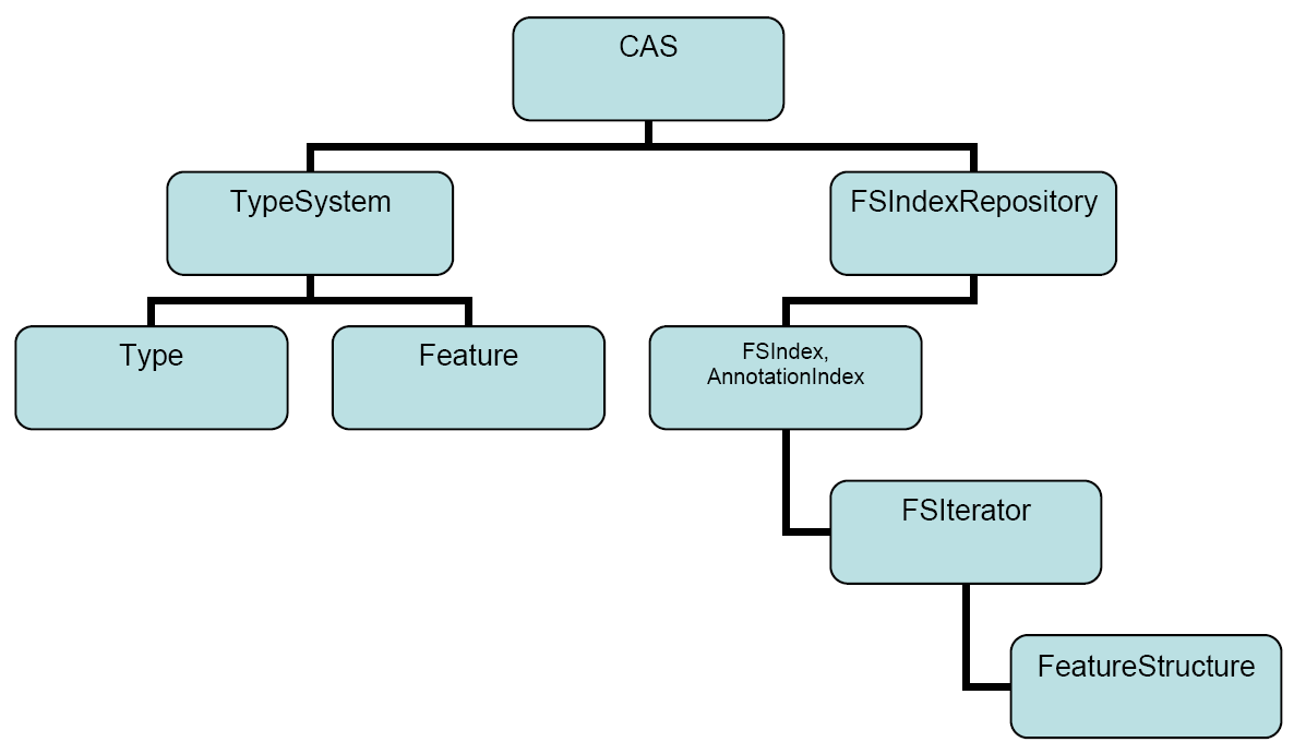
The main Interface is the CAS interface. This has most of the functionality of the CAS, except for the type system metadata access, and the indexing access. JCas and CAS are alternative representations and API approaches to the CAS; each has a method to get the other. You can mix JCas and CAS APIs in your application as needed. To use the JCas APIs, you have to create the Java classes that correspond to the CAS types, and include them in the Java class path of the application. If you have a CAS object, you can get a JCas object by using the getJCas() method call on the CAS object; likewise, you can get the CAS object from a JCas by using the getCAS() method call on the JCas object. There is also a low level CAS interface that is not part of the official API, and is intended for internal use only – it is not documented here.
The type system metadata APIs are found in the TypeSystem interface. The objects defining each type and feature are defined by the interfaces Type and Feature. The Type interface has methods to see what types subsume other types, to iterate over the types available, and to extract information about the types, including what features it has. The Feature interface has methods that get what type it belongs to, its name, and its range (the kind of values it can hold).
The FSIndexRepository gives you access to methods to get instances of indexes, and
also provides access to the iterator over all indexed feature structures:
getAllIndexedFS(aType).
The FSIndex and AnnotationIndex objects give you methods to create instances of
iterators.
Iterators and the CAS methods that create new feature structures return FeatureStructure objects. These objects can be used to set and get the values of defined features within them.
[5] A fourth part, the Subject of Analysis, is discussed in Chapter 5, Annotations, Artifacts, and Sofas.
[6] The name “feature structure” comes from terminology used in linguistics.
Chapter 5. JCas Reference
The CAS is a system for sharing data among annotators, consisting of data structures (definable at run time), sets of indexes over these data, metadata describing these, subjects of analysis, and a high performance serialization/deserialization mechanism. JCas provides Java approach to accessing CAS data, and is based on using generated, specific Java classes for each CAS type.
Annotators process one CAS per call to their process method. During processing, annotators can retrieve feature structures from the passed in CAS, add new ones, modify existing ones, and use and update CAS indexes. Of course, an annotator can also use plain Java Objects in addition; but the data in the CAS is what is shared among annotators within an application.
All the facilities present in the APIs for the CAS are available when using the JCas APIs; indeed, you can use the getCas() method to get the corresponding CAS object from a JCas (and vice-versa). The JCas APIs often have helper methods that make using this interface more convenient for Java developers.
The data in the CAS are typed objects having fields. JCas uses a set of generated Java classes (each corresponding to a particular CAS type) with “getter” and “setter” methods for the features, plus a constructor so new instances can be made. The Java classes don't actually store the data in the class instance; instead, the getters and setters forward to the underlying CAS data representation. Because of this, applications which use the JCas interface can share data with annotators using plain CAS (i.e., not using the JCas approach).
Users can modify the JCas generated Java classes by adding fields to them; this allows arbitrary non-CAS data to also be represented within the JCas objects, as well; however, the non-CAS data stored in the JCas object instances cannot be shared with annotators using the plain CAS.
Data in the CAS initially has no corresponding JCas type instances; these are created as needed at the first reference. This means, if your annotator is passed a large CAS having millions of CAS feature structures, but you only reference a few of them, and no previously created Java JCas object instances were created by upstream annotators, the only Java objects that will be created will be those that correspond to the CAS feature structures that you reference.
The JCas class Java source files are generated from XML type system descriptions. The JCasGen utility does the work of generating the corresponding Java Class Model for the CAS types. There are a variety of ways JCasGen can be run; these are described later. You include the generated classes with your UIMA component, and you can publish these classes for others who might want to use your type system.
The specification of the type system in XML can be written using a conventional text editor, an XML editor, or using the Eclipse plug-in that supports editing UIMA descriptors.
Changes to the type system are done by changing the XML and regenerating the corresponding Java Class Models. Of course, once you've published your type system for others to use, you should be careful that any changes you make don't adversely impact the users. Additional features can be added to existing types without breaking other code.
A separate Java class is generated for each type; this type implements the CAS FeatureStructure interface, as well as having the special getters and setters for the included features. In the current implementation, an additional helper class per type is also generated. The generated Java classes have methods (getters and setters) for the fields as defined in the XML type specification. Descriptor comments are reflected in the generated Java code as Java-doc style comments.
5.1. Name Spaces
Full Type names consist of a “namespace” prefix dotted with a simple name. Namespaces are used like packages to avoid collisions between types that are defined by different people at different times. The namespace is used as the Java package name for generated Java files.
Type names used in the CAS correspond to the generated Java classes directly. If the CAS name is com.myCompany.myProject.ExampleClass, the generated Java class is in the package com.myCompany.myProject, and the class is ExampleClass.
An exception to this rule is the built-in types
starting with uima.cas and uima.tcas;
these names are mapped to Java packages named
org.apache.uima.jcas.cas and
org.apache.uima.jcas.tcas.
5.2. XML description element
Each XML type specification can have <description ... > tags. The description for a type will be copied into the generated Java code, as a Javadoc style comment for the class. When writing these descriptions in the XML type specification file, you might want to use html tags, as allowed in Javadocs.
If you use the Component Description Editor, you can write the html tags normally, for instance, “<h1>My Title</h1>”. The Component Descriptor Editor will take care of coverting the actual descriptor source so that it has the leading “<” character written as “<”, to avoid confusing the XML type specification. For example, <p> would be written in the source of the descriptor as <p>. Any characters used in the Javadoc comment must of course be from the character set allowed by the XML type specification. These specifications often start with the line <?xml version=“1.0” encoding=“UTF-8” ?>, which means you can use any of the UTF-8 characters.
5.3. Mapping built-in CAS types to Java types
The built-in primitive CAS types map to Java types as follows:
uima.cas.Boolean → boolean
uima.cas.Byte    → byte
uima.cas.Short   → short
uima.cas.Integer → int
uima.cas.Long    → long
uima.cas.Float   → float
uima.cas.Double  → double
uima.cas.String  → String
5.4. Augmenting the generated Java Code
The Java Class Models generated for each type can be augmented by the user. Typical augmentations include adding additional (non-CAS) fields and methods, and import statements that might be needed to support these. Commonly added methods include additional constructors (having different parameter signatures), and implementations of toString().
To augment the code, just edit the generated Java source code for the class named the same as the CAS type. Here's an example of an additional method you might add; the various getter methods are retrieving values from the instance:
public String toString() { // for debugging
  return "XsgParse "
    + getslotName() + ": "
    + getheadWord().getCoveredText()
    + " seqNo: " + getseqNo()
    + ", cAddr: " + id
    + ", size left mods: " + getlMods().size()
    + ", size right mods: " + getrMods().size();
}
5.4.1. Persistence of additional data
If you add custom instance fields to JCas cover classes, these exist in the JCas cover object instance, but not in the CAS itself. Each time a CAS object is referenced (by an iterator, or by following a Feature Structure reference), a new JCas cover object instance may be created. If you need these values, you can (a) make them CAS values if possible, or (b) hold a reference to the the particular JCas cover object instance in your Java code. For some simple cases, setting the the performance tuning option JCAS_CACHE_ENABLE (see Section 3.9, “Performance Tuning Options”) to true will cause the same JCas cover object that was previously used for a particular CAS Feature Structure to be reused. However, this capability won't work when other factors interfere with the ability to reuse the same object. Pear isolation is an example of this.
Because of this, and because the JCas Cache holds on to the JCas cover objects beyond their useful life and prevents them from being garbage collected, it is normally recommended running with the JCAS_CACHE_ENABLE set to "false".
5.4.2. Keeping hand-coded augmentations when regenerating
If the type system specification changes, you have to re-run the JCasGen generator. This will produce updated Java for the Class Models that capture the changed specification. If you have previously augmented the source for these Java Class Models, your changes must be merged with the newly (re)generated Java source code for the Class Models. This can be done by hand, or you can run the version of JCasGen that is integrated with Eclipse, and use automatic merging that is done using Eclipse's EMF plug-in. You can obtain Eclipse and the needed EMF plug-in from http://www.eclipse.org/.
If you run the generator version that works without using Eclipse, it will not merge Java source changes you may have previously made; if you want them retained, you'll have to do the merging by hand.
The Java source merging will keep additional constructors, additional fields, and any changes you may have made to the readObject method (see below). Merging will not delete classes in the target corresponding to deleted CAS types, which no longer are in the source – you should delete these by hand.
Warning
The merging supports Java 1.4 syntactic constructs only. JCasGen generates Java 1.4 code, so as long as any code you change here also sticks to only Java 1.4 constructs, the merge will work. If you use Java 5 or later specific syntax or constructs, the merge operation will likely fail to merge properly.
5.4.3. Additional Constructors
Any additional constructors that you add must include the JCas argument. The first line of your constructor is required to be
this(jcas); // run the standard constructor
where jcas is the passed in JCas reference. If the type you're defining
extends uima.tcas.Annotation, JCasGen will automatically
add a constructor which takes 2 additional parameters – the begin and end Java
int values, and set the uima.tcas.Annotation
begin and end fields.
Here's an example: If you're defining a type MyType which has a feature parent, you might make an additional constructor which has an additional argument of parent:
MyType(JCas jcas, MyType parent) {
  this(jcas);        // run the standard constructor
  setParent(parent); // set the parent field from the parameter
}
5.4.3.1. Using readObject
Fields defined by augmenting the Java Class Model to include additional fields represent data that exist for this class in Java, in a local JVM (Java Virtual Machine), but do not exist in the CAS when it is passed to other environments (for example, passing to a remote annotator).
A problem can arise when new instances are created, perhaps by the underlying system when it iterates over an index, which is: how to insure that any additional non-CAS fields are properly initialized. To allow for arbitrary initialization at instance creation time, an initialization method in the Java Class Model, called readObject is used. The generated default for this method is to do nothing, but it is one of the methods that you can modify – to do whatever initialization might be needed. It is called with 0 parameters, during the constructor for the object, after the basic object fields have been set up. It can refer to fields in the CAS using the getters and setters, and other fields in the Java object instance being initialized.
A pre-existing CAS feature structure could exist if a CAS was being passed to this annotator; in this case the JCas system calls the readObject method when creating the corresponding Java instance for the first time for the CAS feature structure. This can happen at two points: when a new object is being returned from an iterator over a CAS index, or a getter method is getting a field for the first time whose value is a feature structure.
5.4.4. Modifying generated items
The following modifications, if made in generated items, will be preserved when regenerating.
The public/private etc. flags associated with methods (getters and setters). You can change the default (“public”) if needed.
“final” or “abstract” can be added to the type itself, with the usual semantics.
5.5. Merging types
Type definitions are merged by the framework from all the components being run together.
5.5.1. Aggregate AEs and CPEs as sources of types
When running aggregate AEs (Analysis Engines), or a set of AEs in a collection processing engine, the UIMA framework will build a merged type system (Note: this “merge” is merging types, not to be confused with merging Java source code, discussed above). This merged type system has all the types of every component used in the application. In addition, application code can use UIMA Framework APIs to read and merge type descriptions, manually.
In most cases, each type system can have its own Java Class Models generated individually, perhaps at an earlier time, and the resulting class files (or .jar files containing these class files) can be put in the class path to enable JCas.
However, it is possible that there may be multiple definitions of the same CAS type, each of which might have different features defined. In this case, the UIMA framework will create a merged type by accumulating all the defined features for a particular type into that type's type definition. However, the JCas classes for these types are not automatically merged, which can create some issues for JCas users, as discussed in the next section.
5.5.2. JCasGen support for type merging
When there are multiple definitions of the same CAS type with different features defined, then JCasGen can be re-run on the merged type system, to create one set of JCas Class definitions for the merged types, which can then be shared by all the components. Directions for running JCasGen can be found in Chapter 8, JCasGen User's Guide. This is typically done by the person who is assembling the Aggregate Analysis Engine or Collection Processing Engine. The resulting merged Java Class Model will then contain get and set methods for the complete set of features. These Java classes must then be made available in the class path, replacing the pre-merge versions of the classes.
If hand-modifications were done to the pre-merge versions of the classes, these must be applied to the merged versions, as described in section Section 5.4.2, “Keeping hand-coded augmentations when regenerating”, above. If just one of the pre-merge versions had hand-modifications, the source for this hand-modified version can be put into the file system where the generated output will go, and the -merge option for JCasGen will automatically merge the hand-modifications with the generated code. If both pre-merged versions had hand-modifications, then these modifications must be manually merged.
An alternative to this is packaging the components as individual PEAR files, each with their own version of the JCas generated Classes. The Framework (as of release 2.2) can run PEAR files using the pear file descriptor, and supply each component with its particular version of the JCas generated class.
5.5.3. Impact of Type Merging on Composability of Annotators
The recommended approach in UIMA is to build and maintain type systems as separate components, which are imported by Annotators. Using this approach, Type Merging does not occur because the Type System and its JCas classes are centrally managed and shared by the annotators.
If you do choose to create a JCas Annotator that relies on Type Merging (meaning that your annotator redefines a Type that is already in use elsewhere, and adds its own features), this can negatively impact the reusability of your annotator, unless your component is used as a PEAR file.
If not using PEAR file packaging isolation capability, whenever anyone wants to combine your annotator with another annotator that uses a different version of the same Type, they will need to be aware of all of the issues described in the previous section. They will need to have the know-how to re-run JCasGen and appropriately set up their classpath to include the merged Java classes and to not include the pre-merge classes. (To enable this, you should package these classes separately from other .jar files for your annotator, so that they can be more easily excluded.) And, if you have done hand-modifications to your JCas classes, the person assembling your annotator will need to properly merge those changes. These issues significantly complicate the task of combining annotators, and will cause your annotator not to be as easily reusable as other UIMA annotators.
5.5.4. Adding Features to DocumentAnnotation
There is one built-in type, uima.tcas.DocumentAnnotation,
to which applications can add additional features. (All other built-in types
are "feature-final" and you cannot add additional features to them.) Frequently,
additional features are added to uima.tcas.DocumentAnnotation
to provide a place to store document-level metadata.
For the same reasons mentioned in the previous section, adding features to
DocumentAnnotation is not recommended if you are using JCas. Instead, it is recommended
that you define your own type for storing your document-level metadata. You can create
an instance of this type and add it to the indexes in the usual way. You can then
retrieve this instance using the iterator returned from the methodgetAllIndexedFS(type)
on an instance of a JFSIndexRepository object.
(As of UIMA v2.1, you do not have to declare a custom index in your descriptor to
get this to work).
If you do choose to add features to DocumentAnnotation, there are additional issues to
be aware of. The UIMA SDK provides the JCas cover class for the built-in definition of
DocumentAnnotation, in the separate jar file uima-document-annotation.jar.
If you add additional features to DocumentAnnotation, you must remove this jar file
from your classpath, because you will not want to use the default JCas cover class.
You will need to re-run JCasGen as described in Section 5.5.2, “JCasGen support for type merging”. JCasGen will generate a new cover
class for DocumentAnnotation, which you must place in your classpath in lieu of the version
in uima-document-annotation.jar.
Also, this is the reason why the method JCas.getDocumentAnnotationFs() returns
type TOP, rather than type DocumentAnnotation. Because the
DocumentAnnotation class can be replaced by users, it is not part of
uima-core.jar and so the core UIMA framework cannot have any references
to it. In your code, you may “cast” the result of JCas.getDocumentAnnotationFs()
to type DocumentAnnotation, which must be available on the classpath either via
uima-document-annotation.jar or by including a custom version that you have generated using JCasGen.
5.6. Using JCas within an Annotator
To use JCas within an annotator, you must include the generated Java classes output from JCasGen in the class path.
An annotator written using JCas is built by defining a class for the annotator that extends JCasAnnotator_ImplBase. The process method for this annotator is written
public void process(JCas jcas)
     throws AnalysisEngineProcessException {
  ... // body of annotator goes here
}
The process method is passed the JCas instance to use as a parameter.
The JCas reference is used throughout the annotator to refer to the particular JCas instance being worked on. In pooled or multi-threaded implementations, there will be a separate JCas for each thread being (simultaneously) worked on.
You can do several kinds of operations using the JCas APIs: create new feature structures (instances of CAS types) (using the new operator), access existing feature structures passed to your annotator in the JCas (for example, by using the next method of an iterator over the feature structures), get and set the fields of a particular instance of a feature structure, and add and remove feature structure instances from the CAS indexes. To support iteration, there are also functions to get and use indexes and iterators over the instances in a JCas.
5.6.1. Creating new instances using the Java “new” operator
The new operator creates new instances of JCas types. It takes at least one parameter, the JCas instance in which the type is to be created. For example, if there was a type Meeting defined, you can create a new instance of it using:
Meeting m = new Meeting(jcas);
Other variations of constructors can be added in custom code; the single parameter version is the one automatically generated by JCasGen. For types that are subtypes of Annotation, JCasGen also generates an additional constructor with additional “begin” and “end” arguments.
5.6.2. Getters and Setters
If the CAS type Meeting had fields location and time, you could get or set these by using getter or setter methods. These methods have names formed by splicing together the word “get” or “set” followed by the field name, with the first letter of the field name capitalized. For instance
getLocation()
The getter forms take no parameters and return the value of the field; the setter forms take one parameter, the value to set into the field, and return void.
There are built-in CAS types for arrays of integers, strings, floats, and feature structures. For fields whose values are these types of arrays, there is an alternate form of getters and setters that take an additional parameter, written as the first parameter, which is the index in the array of an item to get or set.
5.6.3. Obtaining references to Indexes
The only way to access instances (not otherwise referenced from other instances) passed in to your annotator in its JCas is to use an iterator over some index. Indexes in the CAS are specified in the annotator descriptor. Indexes have a name; text annotators have a built-in, standard index over all annotations.
To get an index, first get the JFSIndexRepository from the JCas using the method jcas.getJFSIndexRepository(). Here are the calls to get indexes:
JFSIndexRepository ir = jcas.getJFSIndexRepository();

ir.getIndex(name-of-index) // get the index by its name, a string
ir.getIndex(name-of-index, Foo.type) // filtered by specific type

ir.getAnnotationIndex()      // get AnnotationIndex
ir.getAnnotationIndex(Foo.type)      // filtered by specific type
For convenience, the getAnnotationIndex method is available directly on the JCas object instance; the implementation merely forwards to the associated index repository.
Filtering types have to be a subtype of the type specified for this index in its index specification. They can be written as either Foo.type or if you have an instance of Foo, you can write
fooInstance.jcasType.casType.
Foo is (of course) an example of the name of the type.
5.6.4. Adding (and removing) instances to (from) indexes
CAS indexes are maintained automatically by the CAS. But you must add any instances of feature structures you want the index to find, to the indexes by using the call:
myInstance.addToIndexes();
Do this after setting all features in the instance which could be used in indexing, for example, in determining the sorting order. After indexing, do not change the values of these particular features because the indexes will not be updated. If you need to change the values, you must first remove the instance from the CAS indexes, change the values, and then add the instance back. To remove an instance from the indexes, use the method:
myInstance.removeFromIndexes();
Note
It's OK to change feature values which are not used in determining sort ordering (or set membership), without removing and re-adding back to the index.
When writing a Multi-View component, you may need to index instances in multiple
CAS views. The methods above use the indexes associated with the current JCas object.
There is a variation of the addToIndexes / removeFromIndexes methods which
takes one argument: a reference to a JCas object holding the view in which you want to
index this instance.
myInstance.addToIndexes(anotherJCas)
myInstance.removeFromIndexes(anotherJCas)
You can also explicitly add instances to other views using the addFsToIndexes method on other JCas (or CAS) objects. For instance, if you had 2 other CAS views (myView1 and myView2), in which you wanted to index myInstance, you could write:
myInstance.addToIndexes(); //addToIndexes used with the new operator
myView1.addFsToIndexes(myInstance); // index myInstance in myView1
myView2.addFsToIndexes(myInstance); // index myInstance in myView2
The rules for determining which index to use with a particular JCas object are designed to behave the way most would think they should; if you need specific behavior, you can always explicitly designate which view the index adding and removing operations should work on.
The rules are: If the instance is a subtype of AnnotationBase, then the view is the view associated with the annotation as specified in the feature holding the view reference in AnnotationBase. Otherwise, if the instance was created using the "new" operator, then the view is the view passed to the instance's constructor. Otherwise, if the instance was created by getting a feature value from some other instance, whose range type is a feature structure, then the view is the same as the referring instance. Otherwise, if the instance was created by any of the Feature Structure Iterator operations over some index, then it is the view associated with the index.
5.6.5. Using Iterators
Once you have an index obtained from the JCas, you can get an iterator from the index; here is an example:
FSIndexRepository ir = jcas.getFSIndexRepository();
FSIndex myIndex = ir.getIndex("myIndexName");
FSIterator myIterator = myIndex.iterator();

JFSIndexRepository ir = jcas.getJFSIndexRepository();
FSIndex myIndex = ir.getIndex("myIndexName", Foo.type); // filtered
FSIterator myIterator = myIndex.iterator();
Iterators work like normal Java iterators, but are augmented to support additional capabilities. Iterators are described in the CAS Reference, Section 4.7, “Indexes and Iterators”.
5.6.6. Class Loaders in UIMA
The basic concept of a UIMA application includes assembling engines into a flow. The application made up of these Engines are run within the UIMA Framework, either by the Collection Processing Manager, or by using more basic UIMA Framework APIs.
The UIMA Framework exists within a JVM (Java Virtual Machine). A JVM has the capability to load multiple applications, in a way where each one is isolated from the others, by using a separate class loader for each application. For instance, one set of UIMA Framework Classes could be shared by multiple sets of application - specific classes, even if these application-specific classes had the same names but were different versions.
5.6.6.1. Use of Class Loaders is optional
The UIMA framework will use a specific ClassLoader, based on how ResourceManager instances are used. Specific ClassLoaders are only created if you specify an ExtensionClassPath as part of the ResourceManager. If you do not need to support multiple applications within one UIMA framework within a JVM, don't specify an ExtensionClassPath; in this case, the classloader used will be the one used to load the UIMA framework - usually the overall application class loader.
Of course, you should not run multiple UIMA applications together, in this
way, if they have different class definitions for the same class name. This
includes the JCas “cover” classes. This case might arise, for
instance, if both applications extended
uima.tcas.DocumentAnnotation in differing,
incompatible ways. Each application would need its own definition of this class,
but only one could be loaded (unless you specify ExtensionClassPath in the
ResourceManager which will cause the UIMA application to load its private
versions of its classes, from its classpath).
5.6.7. Issues accessing JCas objects outside of UIMA Engine Components
If you are using the ExtensionClassPaths, the JCas cover classes are loaded under a class loader created by the ResourceManager part of the UIMA Framework. If you reference the same JCas classes outside of any UIMA component, for instance, in top level application code, the JCas classes used by that top level application code also must be in the class path for the application code.
Alternatively, you could do all the JCas processing inside a UIMA component (and do no processing using JCas outside of the UIMA pipeline).
5.7. Setting up Classpath for JCas
The JCas Java classes generated by JCasGen are typically compiled and put into a JAR file, which, in turn, is put into the application's class path.
This JAR file must be generated from the application's merged type system. This is most conveniently done by opening the top level descriptor used by the application in the Component Descriptor Editor tool, and pressing the Run-JCasGen button on the Type System Definition page.
5.8. PEAR isolation
As of version 2.2, the framework supports component descriptors which are PEAR descriptors. These descriptors define components plus include information on the class path needed to run them. The framework uses the class path information to set up a localized class path, just for code running within the PEAR context. This allows PEAR files requiring different versions of common code to work well together, even if the class names in the different versions have the same names.
The mechanism used to switch the class loaders when entering a PEAR-packaged annotator in
a flow depends on the framework knowing if JCas is being used within that annotator code. The
framework will know this if the particular view being passed has had a previous call to
getJCas(), or if the particular annotator is marked as a JCas-using one (by having it extend the
class JCasAnnotator_ImplBase).
Chapter 6. PEAR Reference
A PEAR (Processing Engine ARchive) file is a standard package for UIMA components. This chapter describes the PEAR 1.0 structure and specification.
The PEAR package can be used for distribution and reuse by other components or applications. It also allows applications and tools to manage UIMA components automatically for verification, deployment, invocation, testing, etc.
Currently, there is an Eclipse plugin and a command line tool available to create PEAR packages for standard UIMA components. Please refer to Chapter 9, PEAR Packager User's Guide for more information about these tools.
PEARs distributed to new targets can be installed at those targets. UIMA includes a tool for installing PEARs; see Chapter 11, PEAR Installer User's Guide for more information about installing PEARs.
An installed PEAR can be used as a component within a UIMA pipeline, by specifying the pear descriptor that is created when installing the pear. See Section 6.3, “PEAR package descriptor”.
6.1. Packaging a UIMA component
For the purpose of describing the process of creating a PEAR file and its internal structure, this section describes the steps used to package a UIMA component as a valid PEAR file. The PEAR packaging process consists of the following steps:
6.1.1. Creating the PEAR structure
The first step in the PEAR creation process is to create a PEAR structure. The PEAR structure is a structured tree of folders and files, including the following elements:
-
Required Elements:
-
The metadata folder which contains the PEAR installation descriptor and properties files.
-
The installation descriptor ( metadata/install.xml )
-
A UIMA analysis engine descriptor and its required code, delegates (if any), and resources
-
-
Optional Elements:
-
The desc folder to contain descriptor files of analysis engines, delegates analysis engines (all levels), and other components (Collection Readers, CAS Consumers, etc).
-
The src folder to contain the source code
-
The bin folder to contain executables, scripts, class files, dlls, shared libraries, etc.
-
The lib folder to contain jar files.
-
The doc folder containing documentation materials, preferably accessible through an index.html.
-
The data folder to contain data files (e.g. for testing).
-
The conf folder to contain configuration files.
-
The resources folder to contain other resources and dependencies.
-
Other user-defined folders or files are allowed, but should be avoided.
-
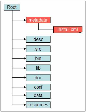
6.1.2. Populating the PEAR structure
After creating the PEAR structure, the component's descriptor files, code files, resources files, and any other files and folders are copied into the corresponding folders of the PEAR structure. The developer should make sure that the code would work with this layout of files and folders, and that there are no broken links. Although it is strongly discouraged, the optional elements of the PEAR structure can be replaced by other user defined files and folder, if required for the component to work properly.
Note
The PEAR structure must be self-contained. For example, this means that the component must run properly independently from the PEAR root folder location. If the developer needs to use an absolute path in configuration or descriptor files, then he/she should put these files in the “conf” or “desc” and replace the path of the PEAR root folder with the string “$main_root” . The tools that deploy and use PEAR files should localize the files in the “conf” and “desc” folders by replacing the string “$main_root” with the local absolute path of the PEAR root folder. The “$main_root” macro can also be used in the Installation descriptor (install.xml)
Currently there are three types of component packages depending on their deployment:
6.1.2.1. Standard Type
A component package with the standard type must be a valid Analysis Engine, and all the required files to deploy it locally must be included in the PEAR package.
6.1.2.2. Service Type
A component package with the service type must be deployable locally as a supported UIMA service (e.g. Vinci). In this case, all the required files to deploy it locally must be included in the PEAR package.
6.1.2.3. Network Type
A component package with the network type is not deployed locally but rather in the “remote” environment. It's accessed as a network AE (e.g. Vinci Service). The component owner has the responsibility to start the service and make sure it's up and running before it's used by others (like a webmaster that makes sure the web site is up and running). In this case, the PEAR package does not have to contain files required for deployment, but must contain the network AE descriptor (see Section 1.1.4, “Creating the XML Descriptor” ) and the <DESC> tag in the installation descriptor must point to the network AE descriptor. For more information about Network Analysis Engines, please refer to Section 3.6, “Working with Remote Services” .
6.1.3. Creating the installation descriptor
The installation descriptor is an xml file called install.xml under the metadata folder of the PEAR structure. It's also called InsD. The InsD XML file should be created in the UTF-8 file encoding. The InsD should contain the following sections:
-
<OS>: This section is used to specify supported operating systems
-
<TOOLKITS>: This section is used to specify toolkits, such as JDK, needed by the component.
-
<SUBMITTED_COMPONENT>: This is the most important section in the Installation Descriptor. It's used to specify required information about the component. See Section 6.1.4, “Installation Descriptor: template” for detailed information about this section.
-
<INSTALLATION>: This section is explained in section Section 6.2, “Installing a PEAR package” .
6.1.4. Documented template for the installation descriptor:
The following is a sample “documented template” which describes content of the installation descriptor install.xml:
<? xml version="1.0" encoding="UTF-8"?>
<!-- Installation Descriptor Template -->
<COMPONENT_INSTALLATION_DESCRIPTOR>
  <!-- Specifications of OS names, including version, etc. -->
  <OS>
    <NAME>OS_Name_1</NAME>
    <NAME>OS_Name_2</NAME>
  </OS>
  <!-- Specifications of required standard toolkits -->
  <TOOLKITS>
    <JDK_VERSION>JDK_Version</JDK_VERSION>
  </TOOLKITS>

  <!-- There are 2 types of variables that are used in the InsD:
       a) $main_root , which will be substituted with the real path to the
                 main component root directory after installing the
                 main (submitted) component
       b) $component_id$root, which will be substituted with the real path
          to the root directory of a given delegate component after
          installing the given delegate component -->

  <!-- Specification of submitted component (AE)             -->
  <!-- Note: submitted_component_id is assigned by developer; -->
  <!--       XML descriptor file name is set by developer.    -->
  <!-- Important: ID element should be the first in the       -->
  <!--            SUBMITTED_COMPONENT section.                -->
  <!-- Submitted component may include optional specification -->
  <!-- of Collection Reader that can be used for testing the  -->
  <!-- submitted component.                                   -->
  <!-- Submitted component may include optional specification -->
  <!-- of CAS Consumer that can be used for testing the       -->
  <!-- submitted component.                                   -->

  <SUBMITTED_COMPONENT>
    <ID>submitted_component_id</ID>
    <NAME>Submitted component name</NAME>
    <DESC>$main_root/desc/ComponentDescriptor.xml</DESC>

    <!-- deployment options:                                   -->
    <!-- a) "standard" is deploying AE locally                 -->
    <!-- b) "service"  is deploying AE locally as a service,   -->
    <!--    using specified command (script)                   -->
    <!-- c) "network"  is deploying a pure network AE, which   -->
    <!--    is running somewhere on the network                -->

    <DEPLOYMENT>standard | service | network</DEPLOYMENT>

    <!-- Specifications for "service" deployment option only   -->
    <SERVICE_COMMAND>$main_root/bin/startService.bat</SERVICE_COMMAND>
    <SERVICE_WORKING_DIR>$main_root</SERVICE_WORKING_DIR>
    <SERVICE_COMMAND_ARGS>

      <ARGUMENT>
        <VALUE>1st_parameter_value</VALUE>
        <COMMENTS>1st parameter description</COMMENTS>
      </ARGUMENT>

      <ARGUMENT>
        <VALUE>2nd_parameter_value</VALUE>
        <COMMENTS>2nd parameter description</COMMENTS>
      </ARGUMENT>

    </SERVICE_COMMAND_ARGS>

    <!-- Specifications for "network" deployment option only   -->

    <NETWORK_PARAMETERS>
      <VNS_SPECS VNS_HOST="vns_host_IP" VNS_PORT="vns_port_No" />
    </NETWORK_PARAMETERS>

    <!-- General specifications                                -->

    <COMMENTS>Main component description</COMMENTS>

    <COLLECTION_READER>
      <COLLECTION_ITERATOR_DESC>
        $main_root/desc/CollIterDescriptor.xml
      </COLLECTION_ITERATOR_DESC>

      <CAS_INITIALIZER_DESC>
        $main_root/desc/CASInitializerDescriptor.xml
      </CAS_INITIALIZER_DESC>
    </COLLECTION_READER>

    <CAS_CONSUMER>
      <DESC>$main_root/desc/CASConsumerDescriptor.xml</DESC>
    </CAS_CONSUMER>

  </SUBMITTED_COMPONENT>
  <!-- Specifications of the component installation process -->
  <INSTALLATION>
    <!-- List of delegate components that should be installed together -->
    <!-- with the main submitted component (for aggregate components)  -->
    <!-- Important: ID element should be the first in each             -->

    <!--            DELEGATE_COMPONENT section.                        -->
    <DELEGATE_COMPONENT>
      <ID>first_delegate_component_id</ID>
      <NAME>Name of first required separate component</NAME>
    </DELEGATE_COMPONENT>

    <DELEGATE_COMPONENT>
      <ID>second_delegate_component_id</ID>
      <NAME>Name of second required separate component</NAME>
    </DELEGATE_COMPONENT>

    <!-- Specifications of local path names that should be replaced -->
    <!-- with real path names after the main component as well as   -->
    <!-- all required delegate (library) components are installed.  -->
    <!-- <FILE> and <REPLACE_WITH> values may use the $main_root or -->
    <!-- one of the $component_id$root variables.                   -->
    <!-- Important: ACTION element should be the first in each      -->
    <!--            PROCESS section.                                -->

    <PROCESS>
      <ACTION>find_and_replace_path</ACTION>
      <PARAMETERS>
        <FILE>$main_root/desc/ComponentDescriptor.xml</FILE>
        <FIND_STRING>../resources/dict/</FIND_STRING>
        <REPLACE_WITH>$main_root/resources/dict/</REPLACE_WITH>
        <COMMENTS>Specify actual dictionary location in XML component
          descriptor
        </COMMENTS>
      </PARAMETERS>
    </PROCESS>

    <PROCESS>
      <ACTION>find_and_replace_path</ACTION>
      <PARAMETERS>
        <FILE>$main_root/desc/DelegateComponentDescriptor.xml</FILE>
        <FIND_STRING>
local_root_directory_for_1st_delegate_component/resources/dict/
        </FIND_STRING>
        <REPLACE_WITH>
          $first_delegate_component_id$root/resources/dict/
        </REPLACE_WITH>
        <COMMENTS>
          Specify actual dictionary location in the descriptor of the 1st
          delegate component
        </COMMENTS>
      </PARAMETERS>
    </PROCESS>

    <!-- Specifications of environment variables that should be set prior
         to running the main component and all other reused components.
         <VAR_VALUE> values may use the $main_root or one of the
         $component_id$root variables. -->

    <PROCESS>
      <ACTION>set_env_variable</ACTION>
      <PARAMETERS>
        <VAR_NAME>env_variable_name</VAR_NAME>
        <VAR_VALUE>env_variable_value</VAR_VALUE>
        <COMMENTS>Set environment variable value</COMMENTS>
      </PARAMETERS>
    </PROCESS>

  </INSTALLATION>
</COMPONENT_INSTALLATION_DESCRIPTOR>
6.1.4.1. The SUBMITTED_COMPONENT section
The SUBMITTED_COMPONENT section of the installation descriptor (install.xml) is used to specify required information about the UIMA component. Before explaining the details, let's clarify the concept of component ID and “macros” used in the installation descriptor. The component ID element should be the first element in the SUBMITTED_COMPONENT section.
The component id is a string that uniquely identifies the component. It should use the JAVA naming convention (e.g. com.company_name.project_name.etc.mycomponent).
Macros are variables such as $main_root, used to represent a string such as the full path of a certain directory.
The values of these macros are defined by the PEAR installation process, when the
PEAR is installed, and represent the values local to that particular installation.
The values are stored in the metadata/PEAR.properties file that is
generated during PEAR installation.
The tools and applications that use and deploy PEAR files replace these macros with
the corresponding values in the local environment as part of the deployment
process in the files included in the conf and desc folders.
Currently, there are two types of macros:
$main_root, which represents the local absolute path of the main component root directory after deployment.
$component_id$root, which represents the local absolute path to the root directory of the component which has component_id as component ID. This component could be, for instance, a delegate component.
For example, if some part of a descriptor needs to have a path to the data
subdirectory of the PEAR, you write $main_root/data. If
your PEAR refers to a delegate component having the ID
“my.comp.Dictionary”, and you need to
specify a path to one of this component's subdirectories, e.g.
resource/dict, you write
$my.comp.Dictionary$root/resources/dict.
6.1.4.2. The ID, NAME, and DESC tags
These tags are used to specify the component ID, Name, and descriptor path using the corresponding tags as follows:
<SUBMITTED_COMPONENT>
  <ID>submitted_component_id</ID>
  <NAME>Submitted component name</NAME>
  <DESC>$main_root/desc/ComponentDescriptor.xml</DESC>
6.1.4.3. Tags related to deployment types
As mentioned before, there are currently three types of PEAR packages, depending on the following deployment types
Standard Type
A component package with the standard type must be a valid UIMA Analysis Engine, and all the required files to deploy it must be included in the PEAR package. This deployment type should be specified as follows:
<DEPLOYMENT>standard</DEPLOYMENT>
Service Type
A component package with the service type must be deployable locally as a supported UIMA service (e.g. Vinci). The installation descriptor must include the path for the executable or script to start the service including its arguments, and the working directory from where to launch it, following this template:
<DEPLOYMENT>service</DEPLOYMENT>
<SERVICE_COMMAND>$main_root/bin/startService.bat</SERVICE_COMMAND>
<SERVICE_WORKING_DIR>$main_root</SERVICE_WORKING_DIR>
<SERVICE_COMMAND_ARGS>
  <ARGUMENT>
    <VALUE>1st_parameter_value</VALUE>
    <COMMENTS>1st parameter description</COMMENTS>
  </ARGUMENT>
  <ARGUMENT>
    <VALUE>2nd_parameter_value</VALUE>
    <COMMENTS>2nd parameter description</COMMENTS>
  </ARGUMENT>
</SERVICE_COMMAND_ARGS>
Network Type
A component package with the network type is not deployed locally, but rather in a “remote” environment. It's accessed as a network AE (e.g. Vinci Service). In this case, the PEAR package does not have to contain files required for deployment, but must contain the network AE descriptor. The <DESC> tag in the installation descriptor (See section 2.3.2.1) must point to the network AE descriptor. Here is a template in the case of Vinci services:
<DEPLOYMENT>network</DEPLOYMENT>
<NETWORK_PARAMETERS>
  <VNS_SPECS VNS_HOST="vns_host_IP" VNS_PORT="vns_port_No" />
</NETWORK_PARAMETERS>
6.1.4.4. The Collection Reader and CAS Consumer tags
These sections of the installation descriptor are used by any specific Collection Reader or CAS Consumer to be used with the packaged analysis engine.
6.1.4.5. The INSTALLATION section
The <INSTALLATION> section specifies the external dependencies of the component and the operations that should be performed during the PEAR package installation.
The component dependencies are specified in the <DELEGATE_COMPONENT> sub-sections, as shown in the installation descriptor template above.
Important: The ID element should be the first element in each <DELEGATE_COMPONENT> sub-section.
The <INSTALLATION> section may specify the following operations:
Setting environment variables that are required to run the installed component.
This is also how you specify additional classpaths for a Java component - by specifying the setting of an environmental variable named CLASSPATH. The
buildComponentClasspathmethod of the PackageBrowser class builds a classpath string from what it finds in the CLASSPATH specification here, plus adds a classpath entry for all Jars in thelibdirectory. Because of this, there is no need to specify Class Path entries for Jars in the lib directory, when using the Eclipse plugin pear packager or the Maven Pear Packager.When specifying the value of the CLASSPATH environment variable, use the semicolon ";" as the separator character, regardless of the target Operating System conventions. This delimiter will be replaced with the right one for the Operating System during PEAR installation.
If your component needs to set the UIMA datapath you must specify the necessary datapath setting using an environment variable with the key
uima.datapath. When such a key is specified thegetComponentDataPathmethod of the PackageBrowser class will return the specified datapath settings for your component.Warning
Do not put UIMA Framework Jars into the lib directory of your PEAR; doing so will cause system failures due to class loading issues.
Note that you can use “macros”, like $main_root or $component_id$root in the VAR_VALUE element of the <PARAMETERS> sub-section.
Finding and replacing string expressions in files.
Note that you can use the “macros” in the FILE and REPLACE_WITH elements of the <PARAMETERS> sub-section.
Important: the ACTION element always should be the 1st element in each <PROCESS> sub-section.
By default, the PEAR Installer will try to process every file in the desc and conf directories of the PEAR package in order to find the “macros” and replace them with actual path expressions. In addition to this, the installer will process the files specified in the <INSTALLATION> section.
Important: all XML files which are going to be processed should be created using UTF-8 or UTF-16 file encoding. All other text files which are going to be processed should be created using the ASCII file encoding.
6.1.5. Packaging the PEAR structure into one file
The last step of the PEAR process is to simply zip the content of the PEAR root folder (not including the root folder itself) to a PEAR file with the extension “.pear”.
To do this you can either use the PEAR packaging tools that are described in “Chapter 9, PEAR Packager User's Guide” or you can use the PEAR packaging API that is shown below.
To use the PEAR packaging API you first have to create the necessary information for the PEAR package:
    //define PEAR data
    String componentID = "AnnotComponentID";
    String mainComponentDesc = "desc/mainComponentDescriptor.xml";
    String classpath ="$main_root/bin;";
    String datapath ="$main_root/resources;";
    String mainComponentRoot = "/home/user/develop/myAnnot";
    String targetDir = "/home/user/develop";
    Properties annotatorProperties = new Properties();
    annotatorProperties.setProperty("sysProperty1", "value1");
To create a complete PEAR package in one step call:
PackageCreator.generatePearPackage(
   componentID, mainComponentDesc, classpath, datapath,
   mainComponentRoot, targetDir, annotatorProperties);
The created PEAR package has the file name <componentID>.pear and is located in the <targetDir>.
To create just the PEAR installation descriptor in the main component root directory call:
PackageCreator.createInstallDescriptor(componentID, mainComponentDesc,
   classpath, datapath, mainComponentRoot, annotatorProperties);
To package a PEAR file with an existing installation descriptor call:
PackageCreator.createPearPackage(componentID, mainComponentRoot,
   targetDir);
The created PEAR package has the file name <componentID>.pear and is located in the <targetDir>.
6.2. Installing a PEAR package
The installation of a PEAR package can be done using the PEAR installer tool (see Chapter 11, PEAR Installer User's Guide, or by an application using the PEAR APIs, directly.
During the PEAR installation the PEAR file is extracted to the installation directory and the PEAR macros in the descriptors are updated with the corresponding path. At the end of the installation the PEAR verification is called to check if the installed PEAR package can be started successfully. The PEAR verification use the classpath, datapath and the system property settings of the PEAR package to verify the PEAR content. Necessary Java library path settings for native libararies, PATH variable settings or system environment variables cannot be recognized automatically and the use must take care of that manually.
Note
By default the PEAR packages are not installed directly to the specified installation directory. For each PEAR a subdirectory with the name of the PEAR's ID is created where the PEAR package is installed to. If the PEAR installation directory already exists, the old content is automatically deleted before the new content is installed.
6.2.1. Installing a PEAR file using the PEAR APIs
The example below shows how to use the PEAR APIs to install a PEAR package and access the installed PEAR package data. For more details about the PackageBrowser API, please refer to the Javadocs for the org.apache.uima.pear.tools package.
File installDir = new File("/home/user/uimaApp/installedPears");
File pearFile = new File("/home/user/uimaApp/testpear.pear");
boolean doVerification = true;

try {
  // install PEAR package
  PackageBrowser instPear = PackageInstaller.installPackage(
 	installDir, pearFile, doVerification);

  // retrieve installed PEAR data
  // PEAR package classpath
  String classpath = instPear.buildComponentClassPath();
  // PEAR package datapath
  String datapath = instPear.getComponentDataPath();
  // PEAR package main component descriptor
  String mainComponentDescriptor = instPear
     	.getInstallationDescriptor().getMainComponentDesc();
  // PEAR package component ID
  String mainComponentID = instPear
     	.getInstallationDescriptor().getMainComponentId();
  // PEAR package pear descriptor
  String pearDescPath = instPear.getComponentPearDescPath();

  // print out settings
  System.out.println("PEAR package class path: " + classpath);
  System.out.println("PEAR package datapath: " + datapath);
  System.out.println("PEAR package mainComponentDescriptor: "
   	+ mainComponentDescriptor);
  System.out.println("PEAR package mainComponentID: "
   	+ mainComponentID);
  System.out.println("PEAR package specifier path: " + pearDescPath);

  } catch (PackageInstallerException ex) {
    // catch PackageInstallerException - PEAR installation failed
    ex.printStackTrace();
    System.out.println("PEAR installation failed");
  } catch (IOException ex) {
    ex.printStackTrace();
    System.out.println("Error retrieving installed PEAR settings");
  }
To run a PEAR package after it was installed using the PEAR API see the example below. It use the generated PEAR specifier that was automatically created during the PEAR installation. For more details about the APIs please refer to the Javadocs.
File installDir = new File("/home/user/uimaApp/installedPears");
File pearFile = new File("/home/user/uimaApp/testpear.pear");
boolean doVerification = true;

try {

  // Install PEAR package
  PackageBrowser instPear = PackageInstaller.installPackage(
  	installDir, pearFile, doVerification);

  // Create a default resouce manager
  ResourceManager rsrcMgr = UIMAFramework.newDefaultResourceManager();

  // Create analysis engine from the installed PEAR package using
  // the created PEAR specifier
  XMLInputSource in =
        new XMLInputSource(instPear.getComponentPearDescPath());
  ResourceSpecifier specifier =
        UIMAFramework.getXMLParser().parseResourceSpecifier(in);
  AnalysisEngine ae =
        UIMAFramework.produceAnalysisEngine(specifier, rsrcMgr, null);

  // Create a CAS with a sample document text
  CAS cas = ae.newCAS();
  cas.setDocumentText("Sample text to process");
  cas.setDocumentLanguage("en");

  // Process the sample document
  ae.process(cas);
  } catch (Exception ex) {
         ex.printStackTrace();
  }
6.3. PEAR package descriptor
To run an installed PEAR package directly in the UIMA framework the pearSpecifier
XML descriptor can be used. Typically during the PEAR installation such an specifier is automatically generated
and contains all the necessary information to run the installed PEAR package. Settings for system environment
variables, system PATH settings or Java library path settings cannot be recognized
automatically and must be set manually when the JVM is started.
Note
The PEAR may contain specifications for "environment variables" and their settings. When such a PEAR is run directly in the UIMA framework, those settings (except for Classpath and Data Path) are converted to Java System properties, and set to the specified values. Java cannot set true environmental variables; if such a setting is needed, the application would need to arrange to do this prior to invoking Java.
The Classpath and Data Path settings are used by UIMA to configure a special Resource Manager that is used when code from this PEAR is being run.
The generated PEAR descriptor is located in the component root directory of the installed PEAR package and has a filename like <componentID>_pear.xml.
The PEAR package descriptor looks like:
<?xml version="1.0" encoding="UTF-8"?>
<pearSpecifier xmlns="http://uima.apache.org/resourceSpecifier">
   <pearPath>/home/user/uimaApp/installedPears/testpear</pearPath>
</pearSpecifier>
The pearPath setting in the descriptor must point to the component root directory
of the installed PEAR package.
Note
It is not possible to share resources between PEAR Analysis Engines that are instantiated using the PEAR descriptor. The PEAR runtime created for each PEAR descriptor has its own specific ResourceManager (unless exactly the same Classpath and Data Path are being used).
Chapter 7. XMI CAS Serialization Reference
This is the specification for the mapping of the UIMA CAS into the XMI (XML Metadata
Interchange[7]) format. XMI is an OMG standard for expressing object graphs in
XML. The UIMA SDK provides support for XMI through the classes
org.apache.uima.cas.impl.XmiCasSerializer and
org.apache.uima.cas.impl.XmiCasDeserializer.
7.1. XMI Tag
The outermost tag is <XMI> and must include a version number and XML namespace attribute:
<xmi:XMI xmi:version="2.0" xmlns:xmi="http://www.omg.org/XMI">
  <!-- CAS Contents here -->
</xmi:XMI>
XML namespaces[8] are used throughout. The “xmi” namespace prefix is used to identify elements and attributes that are defined by the XMI specification. The XMI document will also define one namespace prefix for each CAS namespace, as described in the next section.
7.2. Feature Structures
UIMA Feature Structures are mapped to XML elements. The name of the element is formed from the CAS type name, making use of XML namespaces as follows.
The CAS type namespace is converted to an XML namespace URI by the following rule: replace all dots with slashes, prepend http:///, and append .ecore.
This mapping was chosen because it is the default mapping used by the Eclipse Modeling Framework (EMF)[9] to create namespace URIs from Java package names. The use of the http scheme is a common convention, and does not imply any HTTP communication. The .ecore suffix is due to the fact that the recommended type system definition for a namespace is an ECore model, see Chapter 8, XMI and EMF Interoperability.
Consider the CAS type name “org.myproj.Foo”. The CAS namespace (“org.myorg.”) is converted to the XML namespace URI is http:///org/myproj.ecore.
The XML element name is then formed by concatenating the XML namespace prefix (which is an arbitrary token, but typically we use the last component of the CAS namespace) with the type name (excluding the namespace).
So the example “org.myproj.Foo” FeatureStructure is written to XMI as:
<xmi:XMI
    xmi:version="2.0"
    xmlns:xmi="http://www.omg.org/XMI"
    xmlns:myproj="http:///org/myproj.ecore">
  ...
  <myproj:Foo xmi:id="1"/>
  ...
</xmi:XMI>
The xmi:id attribute is only required if this object will be referred to from elsewhere in the XMI document. If provided, the xmi:id must be unique for each feature.
All namespace prefixes (e.g. “myproj”) in this example must be bound to URIs using the “xmlns...” attribute, as defined by the XML namespaces specification.
7.3. Primitive Features
CAS features of primitive types (String, Boolean, Byte, Short, Integer, Long , Float, or Double) can be mapped either to XML attributes or XML elements. For example, a CAS FeatureStructure of type org.myproj.Foo, with features:
begin   = 14
end     = 19
myFeature = "bar"
could be mapped to:
<xmi:XMI xmi:version="2.0" xmlns:xmi="http://www.omg.org/XMI"
    xmlns:myproj="http:///org/myproj.ecore">
  ...
  <myproj:Foo xmi:id="1" begin="14" end="19" myFeature="bar"/>
  ...
</xmi:XMI>
or equivalently:
<xmi:XMI xmi:version="2.0" xmlns:xmi="http://www.omg.org/XMI"
    xmlns:myproj="http:///org/myproj.ecore">
  ...
  <myproj:Foo xmi:id="1">
    <begin>14</begin>
    <end>19</end>
    <myFeature>bar</myFeature>
  </myproj:Foo>
  ...
</xmi:XMI>
The attribute serialization is preferred for compactness, but either representation is allowable. Mixing the two styles is allowed; some features can be represented as attributes and others as elements.
7.4. Reference Features
CAS features that are references to other feature structures (excluding arrays and lists, which are handled separately) are serialized as ID references.
If we add to the previous CAS example a feature structure of type org.myproj.Baz, with feature “myFoo” that is a reference to the Foo object, the serialization would be:
<xmi:XMI xmi:version="2.0" xmlns:xmi="http://www.omg.org/XMI"
    xmlns:myproj="http:///org/myproj.ecore">
  ...
  <myproj:Foo xmi:id="1" begin="14" end="19" myFeature="bar"/>
  <myproj:Baz xmi:id="2" myFoo="1"/>
  ...
</xmi:XMI>
As with primitive-valued features, it is permitted to use an element rather than an attribute. However, the syntax is slightly different:
<myproj:Baz xmi:id="2">
   <myFoo href="#1"/>
<myproj.Baz>
Note that in the attribute representation, a reference feature is indistinguishable from an integer-valued feature, so the meaning cannot be determined without prior knowledge of the type system. The element representation is unambiguous.
7.5. Array and List Features
For a CAS feature whose range type is one of the CAS array or list types, the XMI serialization depends on the setting of the “multipleReferencesAllowed” attribute for that feature in the UIMA Type System Description (see Section 2.3.3, “Features”).
An array or list with multipleReferencesAllowed = false (the default) is serialized as a “multi-valued” property in XMI. An array or list with multipleReferencesAllowed = true is serialized as a first-class object. Details are described below.
7.5.1. Arrays and Lists as Multi-Valued Properties
In XMI, a multi-valued property is the most natural XMI representation for most cases. Consider the example where the FeatureStructure of type org.myproj.Baz has a feature myIntArray whose value is the integer array {2,4,6}. This can be mapped to:
<myproj:Baz xmi:id="3" myIntArray="2 4 6"/>
or equivalently:
<myproj:Baz xmi:id="3">
  <myIntArray>2</myIntArray>
  <myIntArray>4</myIntArray>
  <myIntArray>6</myIntArray>
</myproj:Baz>
Note that String arrays whose elements contain embedded spaces MUST use the latter mapping.
FSArray or FSList features are serialized in a similar way. For example an FSArray feature that contains references to the elements with xmi:id's “13” and “42” could be serialized as:
<myproj:Baz xmi:id="3" myFsArray="13 42"/>
or:
<myproj:Baz xmi:id="3">
  <myFsArray href="#13"/>
  <myFsArray href="#42"/>
</myproj:Baz>
7.5.2. Arrays and Lists as First-Class Objects
The multi-valued-property representation described in the previous section does not allow multiple references to an array or list object. Therefore, it cannot be used for features that are defined to allow multiple references (i.e. features for which multipleReferencesAllowed = true in the Type System Description).
When multipleReferencesAllowed is set to true, array and list features are serialized as references, and the array or list objects are serialized as separate objects in the XMI. Consider again the example where the FeatureStructure of type org.myproj.Baz has a feature myIntArray whose value is the integer array {2,4,6}. If myIntArray is defined with multipleReferencesAllowed=true, the serialization will be as follows:
<myproj:Baz xmi:id="3" myIntArray="4"/>
or:
<myproj:Baz xmi:id="3">
  <myIntArray href="#4"/>
</myproj:Baz>
with the array object serialized as
<cas:IntegerArray xmi:id="4" elements="2 4 6"/>
or:
<cas:IntegerArray xmi:id="4">
  <elements>2</elements>
  <elements>4</elements>
  <elements>6</elements>
</cas:IntegerArray>
Note that in this case, the XML element name is formed from the CAS type name (e.g.
“uima.cas.IntegerArray”) in the same way as for other
FeatureStructures. The elements of the array are serialized either as a space-separated attribute named
“elements” or as a series of child elements named “elements”.
List nodes are just standard FeatureStructures with “head” and “tail” features, and are serialized using the normal FeatureStructure serialization. For example, an IntegerList with the values 2, 4, and 6 would be serialized as the four objects:
<cas:NonEmptyIntegerList xmi:id="10" head="2" tail="11"/>
<cas:NonEmptyIntegerList xmi:id="11" head="4" tail="12"/>
<cas:NonEmptyIntegerList xmi:id="12" head="6" tail="13"/>
<cas:EmptyIntegerList xmi:id"13"/>
This representation of arrays allows multiple references to an array of list. It also allows a feature with range type TOP to refer to an array or list. However, it is a very unnatural representation in XMI and does not support interoperability with other XMI-based systems, so we instead recommend using the multi-valued-property representation described in the previous section whenever it is possible.
7.5.3. Null Array/List Elements
In UIMA, an element of an FSArray or FSList may be null. In XMI, multi-valued properties do not permit null values. As a workaround for this, we use a dummy instance of the special type cas:NULL, which has xmi:id 0. For example, in the following example the “myFsArray” feature refers to an FSArray whose second element is null:
<cas:NULL xmi:id="0"/>
<myproj:Baz xmi:id="3">
  <myFsArray href="#13"/>
  <myFsArray href="#0"/>
  <myFsArray href="#42"/>
</myproj:Baz>
7.6. Subjects of Analysis (Sofas) and Views
A UIMA CAS contain one or more subjects of analysis (Sofas). These are serialized no differently from any other feature structure. For example:
<?xml version="1.0"?>
<xmi:XMI xmi:version="2.0" xmlns:xmi=http://www.omg.org/XMI
    xmlns:cas="http:///uima/cas.ecore">
  <cas:Sofa xmi:id="1" sofaNum="1"
      text="the quick brown fox jumps over the lazy dog."/>
</xmi:XMI>
Each Sofa defines a separate View. Feature Structures in the CAS can be members of one or more views. (A Feature Structure that is a member of a view is indexed in its IndexRepository, but that is an implementation detail.)
In the XMI serialization, views will be represented as first-class objects. Each View has an (optional) “sofa” feature, which references a sofa, and multi-valued reference to the members of the View. For example:
<cas:View sofa="1" members="3 7 21 39 61"/>
Here the integers 3, 7, 21, 39, and 61 refer to the xmi:id fields of the objects that are members of this view.
7.7. Linking an XMI Document to its Ecore Type System
If the CAS Type System has been saved to an Ecore file (as described in Chapter 8, XMI and EMF Interoperability), it is possible to store a link from an XMI document to that Ecore type system. This is done using an xsi:schemaLocation attribute on the root XMI element.
The xsi:schemaLocation attribute is a space-separated list that represents a mapping from namespace URI (e.g. http:///org/myproj.ecore) to the physical URI of the .ecore file containing the type system for that namespace. For example:
xsi:schemaLocation=
  "http:///org/myproj.ecore file:/c:/typesystems/myproj.ecore"
would indicate that the definition for the org.myproj CAS types is contained in the file
c:/typesystems/myproj.ecore. You can specify a different
mapping for each of your CAS namespaces, using a space separated list. For details see
Budinsky et al. Eclipse Modeling Framework.
7.8. Delta CAS XMI Format
The Delta CAS XMI serialization format is designed primarily to reduce the overhead serialization when calling annotators configured as services. Only Feature Structures and Views that are new or modified by the service are serialized and returned by the service.
The classes org.apache.uima.cas.impl.XmiCasSerializer and
org.apache.uima.cas.impl.XmiCasDeserializer support serialization of only the modifications to the CAS.
A caller is expected to set a marker to indicate the point from which changes to the CAS are to be tracked.
A Delta CAS XMI document contains only the Feature Structures and Views that have been added or modified.
The new and modified Feature Structures are represented in exactly the format as in a complete CAS serialization.
The cas:View element has been extended with three additional attributes to represent modifications to
View membership. These new attributes are added_members, deleted_members and
reindexed_members. For example:
<cas:View sofa="1" added_members="63 77"
          deleted_member="7 61" reindexed_members="39" />
Here the integers 63, 77 represent xmi:id fields of the objects that have been newly added members to this View, 7 and 61 are xmi:id fields of the objects that have been removed from this view and 39 is the xmi:id of an object to be reindexed in this view.